Creality 3D Printer, K1 SE Fully Assembled Auto Leveling FDM 3D Printers for Kids and Beginners, 600mm/s Max High-Speed Printing, Core XY All Metal Structure, Larger Print Size 250x220x220mm
$279.00 (as of June 19, 2025 23:45 GMT +00:00 - More infoProduct prices and availability are accurate as of the date/time indicated and are subject to change. Any price and availability information displayed on [relevant Amazon Site(s), as applicable] at the time of purchase will apply to the purchase of this product.)In the realm of computer-aided design (CAD), the creation of specialized components such as partially threaded screws can significantly contribute to the precision and functionality of engineered products. This article will guide you through the process of fabricating a partially threaded screw within Ondsel, utilizing the FreeCAD Fasteners Workbench. Through a systematic, step-by-step approach, you will learn how to manipulate various aspects of the screw, including its size and thread configuration.
You will begin by selecting the appropriate workbench and inserting a pre-defined screw, followed by transitioning to the Part Design Workbench to further refine its specifications. The tutorial will elucidate the intricacies of thread modeling and body creation, ensuring the screw conforms to desired technical standards. With the assistance of PCBWay’s export functionality, your FreeCAD model can be seamlessly integrated into their manufacturing services, providing a full-circle design-to-production workflow.

Understanding the Objective
Defining a Partially Threaded Screw
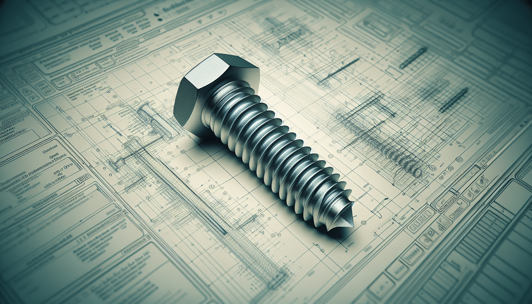
A partially threaded screw is a type of fastener which features threading along part of its length while the other part remains unthreaded, typically smooth. This unthreaded portion allows for more precise clamping force and alignment in mechanical assemblies and is commonly used where two materials need to be held together with specific tension, without the screw threads engaging with the outer material.
Application and Importance in Engineering
In engineering, partially threaded screws are indispensable in applications where precise alignment and controlled tension are critical. They are often used in scenarios involving soft or brittle materials that could be damaged by threads extending through their entire length. In addition, these screws facilitate smoother motion in the unthreaded section, effectively reducing wear and enhancing the longevity of the mechanical system.
Overview of Ondsel and FreeCAD
Ondsel is a collaborative platform designed around FreeCAD, an open-source parametric 3D CAD modeler. FreeCAD is highly versatile, supporting a multitude of engineering tasks from complete product design to complex simulations. Combining Ondsel with FreeCAD provides a robust environment for designing and engineering precise components like partially threaded screws, which are crucial in numerous engineering disciplines.
Introduction to FreeCAD Fasteners Workbench
What is FreeCAD?
FreeCAD is a powerful open-source 3D parametric modeler designed for creating detailed engineering models. Pet-Michel, platform compatibility, and extensive community support make it an attractive tool for both amateurs and professional engineers. It allows users to create, modify, and document 3D parametric models, making it highly suitable for the precise design tasks in engineering.
Installing FreeCAD Fasteners Workbench
To begin with, the FreeCAD Fasteners Workbench must be installed. This specialized workbench provides a collection of standard fasteners and tools for customization. Installation can be easily accomplished through the Addon Manager within FreeCAD. Navigate to Tools > Addon Manager, then search for and install the ‘Fasteners’ plugin. Once installed, restart FreeCAD to access the new workbench.
Navigating the Fasteners Workbench Interface
Upon installing the Fasteners Workbench, familiarizing yourself with its interface is crucial. The workbench includes a toolbar loaded with tools for inserting predefined fasteners like screws, nuts, and washers. The sidebar displays options for customizing dimensions and types of fasteners. Navigating this workspace effectively requires understanding how to insert, modify, and arrange fastener components to fit your specified requirements.
Find 3D Printing Accessories Here
Setting Up the Project in FreeCAD
Starting a New Project
Initiating a new project in FreeCAD involves launching the software and starting with a blank slate. Click File > New to open a new project window. This serves as your workspace where all subsequent modeling tasks will be carried out. Ensure you save your project regularly to prevent data loss, using File > Save As to set a specific file name and location.
Selecting the Appropriate Workbench
FreeCAD hosts multiple workbenches tailored for different modeling tasks. For this tutorial, initially switch to the Fasteners Workbench by selecting it from the drop-down list in the top toolbar. This action prepares your workspace with the necessary tools to start creating and customizing your screw.
Importing or Creating Initial Geometry
Depending on your project needs, you may need to import a reference model or create new geometry. For initial setup, open your referenced design files using File > Import. Alternatively, you can begin designing the required base geometry using tools from the Part or Part Design workbench before moving onto screw customization.
Creating a Standard Screw
Inserting a Predefined Screw from the Fasteners Workbench
In the Fasteners Workbench, click on the “Screw” icon in the toolbar to insert a predefined screw into your project. A dialog will appear, prompting you to choose from various types of screws like ISO, DIN, or ANSI standards. Select the desired type to insert the screw into your workspace, aligned to the default axes.
Adjusting Screw Dimensions
Once the screw is inserted, you can modify its dimensions to meet your specifications. Click on the inserted screw to activate its properties in the sidebar. Dimensions such as length, diameter, and thread pitch can be adjusted by entering the precise values in the designated fields. This step ensures that the screw fits within the tolerance and design requirements of your engineering project.
Choosing Screw Type and Size
Choosing the correct type and size of the screw is essential for ensuring compatibility with the intended application. The selection process involves understanding thread standards, head types, and material properties. Utilize the properties panel in the Fasteners Workbench to choose these characteristics carefully. This ensures the screw will provide optimal performance in your engineering assembly.

Transition to Part Design Workbench
Why Switch to Part Design Workbench?
Switching to the Part Design Workbench becomes necessary when further modifications that involve sketching or creating intricate masks are required. The Part Design Workbench offers a comprehensive set of tools for detailed solid modeling which allows for more complex features like grooving partial threads.
Steps to Switch Workbenches in FreeCAD
To switch to the Part Design Workbench, use the drop-down menu in the top toolbar. Select Part Design from the list to change the interface and toolset accordingly. This workbench provides advanced features suitable for the precise design adjustments required to create a partially threaded screw.
Saving Your Work
Saving your project frequently is crucial to avoid data loss. Use File > Save to save your project in its current state, and File > Save As to save under a different name or location. This ensures that you can revisit and revert to specific stages of your design process if needed.
Modifying the Screw Geometry
Creating a New Body for Modifications
In the Part Design Workbench, the first step to modifying the screw geometry is to create a new body. Click on Create a new body in the toolbar, which organizes all subsequent features and sketches under this new body. This makes the management and sequencing of operations more streamlined and efficient.
Positioning the Screw within the New Body
Positioning is crucial for correct subsequent modifications. Drag the previously inserted screw into the new body by selecting it and using the drag-and-drop functionality within the model tree. Ensure the screw is properly aligned within the new body for accurate modification.
Editing Screw Properties
With the screw now embedded in the new body, editing its properties becomes straightforward. Access the screw’s properties by clicking on it within the model tree. Update dimensions or other attributes such as material or thread characteristics to align with specific design criteria.
Designing the Partial Thread
Creating a Sketch for Thread Removal
To create a partial thread, you need to design a cut that will remove the thread from a specific section of the screw. Start by creating a new sketch in the Part Design Workbench. Click on Create a new sketch and select the plane on which to base your sketch.
Selecting the XZ Plane for Sketching
For this particular task, select the XZ plane when prompted. This plane aligns your sketch along the axis of the screw, ensuring accurate cutting and removal of threads in the desired area.
Using the Rectangle Tool to Define the Thread Cut Area
Use the rectangle tool to define the area of thread removal within the sketch. Start from one edge of the thread and drag the rectangle to encompass the portion you intend to remove. This area will then be used to create a groove that removes the threading, leaving a smooth section behind.
Applying the Groove Feature
Exiting the Sketch Mode
After sketching the area to be removed, exit the sketch mode by clicking the Close button. The sketch should now appear in the model tree linked to the selected plane.
Using the Groove Feature to Cut the Thread
Next, apply the groove feature to remove the defined section of the thread. Select the sketch, then click on the Groove tool within the Part Design Workbench. This tool will revolve the defined sketch around the screw’s axis, effectively cutting away the threads within the sketched region.
Adjusting the Grooved Area
It might be necessary to calibrate the grooved area for precision. After applying the groove, the model can be visually inspected, and adjustments can be made by editing the previously defined sketch. Changing the rectangle dimensions will directly affect the extent of the thread removal.
Final Adjustments and Verifications
Reviewing the Modified Screw
With the groove applied, review the modified screw to ensure it meets the design specifications. Rotate and zoom in on the model in the 3D view to verify the accuracy and completeness of the partial thread.
Making Length Adjustments if Necessary
Sometimes, the overall length of the screw may require fine-tuning after the partial thread has been created. Make any necessary length adjustments by editing the screw’s properties in the Fasteners Workbench or using the Part Design tools.
Verifying the Partial Thread in 3D View
Finally, comprehensively verify the partial thread in the 3D view. Ensure the transition between threaded and unthreaded sections is smooth and precise. This step is critical to confirm that the screw will perform as intended in its final application.
Conclusion
Summary of Steps Covered
In this tutorial, you have learned to create a partially threaded screw using the FreeCAD Fasteners Workbench and the Part Design Workbench. Starting from defining project objectives, installing the necessary tools, setting up your workspace, and finally creating and modifying the screw geometry, each step is crucial for achieving the desired outcome.
Importance of Accurate Thread Design
Accurate thread design is paramount in engineering applications where proper load distribution, alignment, and mechanical fit are critical. A partially threaded screw provides the necessary features to meet these demands, thus highlighting the importance of precision in every step of your design process.
Encouragement to Explore FreeCAD Further
You are encouraged to dive deeper into FreeCAD’s capabilities and explore other workbenches and features. Mastery of this versatile tool can lead to the proficient creation of a wide array of complex engineering models, furthering your capabilities and contributions to the field of engineering.
Maintain Your 3D Printer with these Tools


