Creality K1C 3D Printer, 2024 New Version 3D Printers with 600mm/s Fast Printing Speed, Support Carbon Fiber Filament 300℃ High-Temp Print, Auto Leveling and Clog-Free Direct Extruder
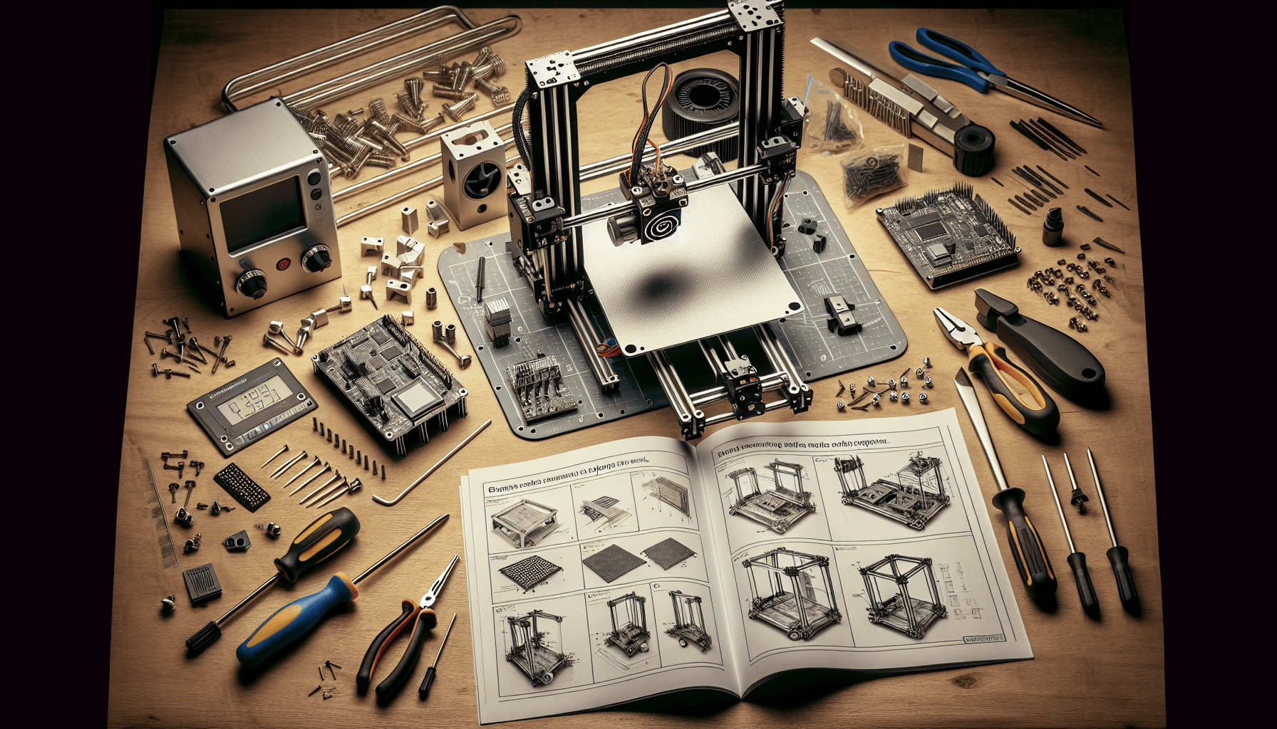
$559.00 (as of June 19, 2025 23:45 GMT +00:00 - More infoProduct prices and availability are accurate as of the date/time indicated and are subject to change. Any price and availability information displayed on [relevant Amazon Site(s), as applicable] at the time of purchase will apply to the purchase of this product.)The article titled “3 Design Tips for Better 3D Printed Holes – CAD For Newbies” is a video tutorial by Maker’s Muse that aims to provide three useful design tips for creating high-quality and accurate holes in 3D printed parts. The video, part of the CAD for Newbies playlist, utilizes Fusion 360 software and showcases the design process of a custom 3D printer inspired by the Fallout video game. The author emphasizes the importance of designing holes with careful consideration for the layer-by-layer process of 3D printing, as well as the potential inaccuracies that may arise. The first tip suggested is to add a teardrop shape to horizontally aligned holes, as this prevents the top part of the hole from flattening and interfering with the insertion of rods. The second tip involves adding a slot to accommodate tight-fitting rods, allowing for slight plastic deformation and subsequent clamping to ensure a secure fit. Lastly, the author discusses using variations of slots or flexible fingers to create conforming holes for components such as bearings. These design tricks and tweaks are aimed at optimizing the outcome of 3D printed holes and improving the overall quality of parts.

Tip 1: Add a teardrop shape to horizontally aligned holes
Explanation of the issue with circular holes in 3D printing
In 3D printing, the layer-by-layer process can result in inaccuracies, particularly in circular holes. When a circular hole is printed layer by layer, it may not turn out perfectly concentric. Instead, it can have flat spots at the top, making it difficult for rods or other objects to fit securely. Even if the hole is close to the desired size, these inaccuracies can cause problems.
Advantages of adding a teardrop shape
To address this issue, one effective design tweak is to incorporate a teardrop shape into horizontally aligned holes. The teardrop shape adds clearance at the top of the hole, allowing the rod or object to fit without any interference. This design modification ensures that the printed part can be used without the need for extra drilling or modifications.
Step-by-step instructions for adding a teardrop shape in CAD software
To add a teardrop shape to a hole in your CAD software, follow these steps:
- Start by creating a circle with a diameter slightly larger than the desired size of the hole.
- Draw two curved lines on either side of the top part of the circle, creating the teardrop shape.
- Ensure that the teardrop shape provides enough clearance for the rod or object to fit. It should be larger than the actual diameter of the rod.
- Once the teardrop shape is complete, extrude or modify the hole in your CAD software as needed.
- Verify the clearance by using a tolerance test gauge or similar tool to ensure that the rod or object fits properly.
By incorporating a teardrop shape into horizontally aligned holes, you can improve the accuracy and quality of your 3D printed parts and ensure a more secure fit for rods and other objects.
Tip 2: Add a slot for tight rod insertion
Benefits of adding a slot for rod insertion
In certain cases, such as when inserting rods that need to fit tightly, it is beneficial to add a slot to the design. This allows the plastic to deform slightly, accommodating the rod and providing a tight fit. By incorporating a slot, you can achieve a more precise and secure connection between the rod and the printed part.
How to determine the amount of clearance needed
Before adding the slot, it is important to determine the amount of clearance required for the rod to fit properly. This will depend on the specific dimensions and tolerances of the rod. It is recommended to leave a small amount of clearance to allow for the deformation of the plastic and ensure a snug fit.
Step-by-step instructions for adding a slot for rod insertion
To add a slot for rod insertion in your CAD software, follow these steps:
- Identify the location where the rod will be inserted.
- Draw a rectangular slot that allows for some deformation of the plastic.
- Determine the appropriate clearance for the slot based on the dimensions and tolerances of the rod.
- Consider adding additional features, such as areas for screws and nuts, to further secure the rod in place.
- Ensure that the slot is appropriately sized to allow for a tight yet flexible fit.
- Modify the design as needed to accommodate the addition of the slot.
- Test the fit and make any necessary adjustments to achieve the desired level of tightness.
By incorporating a slot for rod insertion, you can achieve a precise and secure fit between the rod and the printed part, ensuring optimal functionality and performance.
Find 3D Printing Accessories Here
Tip 3: Use deformable fingers for conforming holes
Explanation of using deformable fingers for accommodating bearings
When designing holes to accommodate bearings, it can be challenging to achieve a perfect fit due to the limitations of FDM (Fused Deposition Modeling) 3D printers. However, by employing a technique known as deformable fingers, it is possible to create holes that conform to the shape of the bearing while still providing a secure fit.
Advantages of using this technique
The use of deformable fingers offers several advantages when designing holes for bearings:
- Improved accuracy: By allowing the plastic to deform slightly, the holes can better conform to the shape of the bearing, resulting in a more precise fit.
- Friction-based locking: The deformable fingers provide increased friction, ensuring that the bearing remains securely in place.
- Simplified design: Despite appearing complex, creating deformable fingers is relatively straightforward in CAD software, making it accessible even for beginners.
Step-by-step instructions for creating deformable fingers in CAD software
To create deformable fingers in CAD software for accommodating bearings, follow these steps:
- Identify the geometry of the bearing and the desired location for the hole.
- Create a projected line or surface to outline the shape of the bearing.
- Draw small circles or other shapes that intersect with the projected line or surface, creating the deformable fingers.
- Remove the excess material, cutting away the area outside the desired hole shape.
- Adjust the dimensions and positions of the deformable fingers as needed to achieve the desired level of flexibility and fit.
By employing the technique of deformable fingers, you can design holes that conform to the shape of bearings, ensuring a secure fit while maximizing accuracy and functionality.
Design considerations for 3D printed parts without support material
Explanation of the challenges of using support material in 3D printing
When designing parts for 3D printing, the use of support material can present challenges. Removing support material can be time-consuming and may result in surface imperfections or damage to the printed part. Therefore, designing parts that do not require support material can streamline the printing process and improve the overall quality of the final product.
Benefits of designing parts to not require support material
There are several benefits to designing parts that do not require support material:
- Time-saving: Removing support material can be a time-consuming process. By designing parts that do not require support, you can significantly reduce the time required for post-processing.
- Enhanced surface quality: Support material removal can sometimes leave behind surface imperfections or damage. Designing parts without support reduces the likelihood of these issues, resulting in a smoother and more aesthetically pleasing finish.
- Improved functionality: Parts that do not require support material are often more structurally sound and perform better in their intended functions. By eliminating the need for support, you can maintain the integrity and strength of the printed part.
Step-by-step instructions for designing parts without support material
To design parts that do not require support material, consider the following steps:
- Identify areas of the design that would typically require support material, such as overhangs or complex geometries.
- Evaluate whether these areas can be modified or redesigned to eliminate the need for support.
- Utilize design techniques such as adding additional structural supports or splitting the model into multiple parts that can be printed separately and assembled.
- Use CAD software to modify the design accordingly, ensuring that the revised version maintains the intended functionality and structural integrity.
- Test the modified design to confirm that it does not require support material and that all dimensions and tolerances are within acceptable ranges.
By incorporating these design considerations and techniques, you can create 3D printed parts that are functional, aesthetically pleasing, and do not require the use of support material.

Conclusion
In conclusion, designing 3D printed parts with accurate and high-quality holes requires careful consideration and strategic design choices. By incorporating the following design tips:
- Adding a teardrop shape to horizontally aligned holes
- Adding a slot for tight rod insertion
- Using deformable fingers for conforming holes
you can significantly improve the accuracy, functionality, and overall quality of your 3D printed parts.
It is important to recognize the limitations and challenges of 3D printing technology and adapt the design process accordingly. By addressing these challenges and integrating design strategies that eliminate the need for support material, you can streamline the printing process and achieve better results.
As 3D printing continues to evolve, it is crucial for designers to consider these strategies and continuously strive for innovation and improvement in their CAD designs. By implementing these tips, you can enhance your design skills and create 3D printed parts with exceptional quality and functionality.
By prioritizing design considerations and applying these tips, you can unlock the full potential of 3D printing technology and create intricate, precise, and functional parts for a variety of applications. Remember to always test and iterate your designs to ensure optimal performance and explore new possibilities in CAD design.
Maintain Your 3D Printer with these Tools
ELEGOO PLA Filament 1.75mm Black 1KG, 3D Printer Filament Dimensional Accuracy +/- 0.02mm, 1kg Cardboard Spool(2.2lbs) 3D Printing Filament Fits for Most FDM 3D Printers
$13.99 (as of June 19, 2025 23:45 GMT +00:00 - More infoProduct prices and availability are accurate as of the date/time indicated and are subject to change. Any price and availability information displayed on [relevant Amazon Site(s), as applicable] at the time of purchase will apply to the purchase of this product.)
OVERTURE PLA Plus (PLA+) Filament 1.75mm, Stronger & More Durable, Professional Toughness 3D Printer Filament 1kg (2.2lbs), High Precision +/- 0.02mm, Tangle-Free (Black)
$20.99 (as of June 19, 2025 23:45 GMT +00:00 - More infoProduct prices and availability are accurate as of the date/time indicated and are subject to change. Any price and availability information displayed on [relevant Amazon Site(s), as applicable] at the time of purchase will apply to the purchase of this product.)
ANYCUBIC Photon Mono 4, Resin 3D Printer with 7'' 10K Mono LCD Screen, Stable LighTurbo Light Source and 70mm/h Fast Printing, Print Volume 6.04'' x 3.42'' x 6.49''
$159.99 (as of June 19, 2025 23:45 GMT +00:00 - More infoProduct prices and availability are accurate as of the date/time indicated and are subject to change. Any price and availability information displayed on [relevant Amazon Site(s), as applicable] at the time of purchase will apply to the purchase of this product.)
Shining 3D Einstar Handheld 3D Scanner with Detail-Oriented Enhancement Technology Support Scanning Hair and Body, Up to 14FPS Scanning Speed High Quality Collecting Data 3D Scanner for 3D Printer
$759.00 (as of June 20, 2025 23:49 GMT +00:00 - More infoProduct prices and availability are accurate as of the date/time indicated and are subject to change. Any price and availability information displayed on [relevant Amazon Site(s), as applicable] at the time of purchase will apply to the purchase of this product.)