Bambu Lab A1 Mini 3D Printer, Support Multi-Color 3D Printing, Set Up in 20 Mins, High Speed & Precision, Full-Auto Calibration & Active Flow Rate Compensation, ≤48 dB Quiet FDM 3D Printers
$399.00 (as of June 18, 2025 23:32 GMT +00:00 - More infoProduct prices and availability are accurate as of the date/time indicated and are subject to change. Any price and availability information displayed on [relevant Amazon Site(s), as applicable] at the time of purchase will apply to the purchase of this product.)In the Blender 2.8 Beginner 3D Modeling Tutorial by tutor4u, viewers are guided through the process of creating a 3D model of a hammer using Blender 2.8 beta. The tutorial covers essential Blender basics such as zooming, panning, selecting objects, moving, scaling, and rotating, before delving into the specific techniques for modeling the hammer. The tutorial demonstrates how to start the modeling process by extruding, scaling, and adding loop cuts, as well as transforming shapes and using subdivision surface modifiers. The tutorial also includes instructions for creating a handle for the hammer, adding geometry to smooth the surface, reshaping the handle, and adding loop cuts for sharp edges. The tutorial concludes by mentioning that the next video in the series will demonstrate how to add materials and textures to the model.
Throughout the tutorial, the tutor emphasizes the use of Blender version 2.8 beta and acknowledges that some functions may differ in earlier versions. The tutorial offers a detailed step-by-step guide, covering various techniques and tools, to assist beginners in their journey to 3D modeling using Blender 2.8 beta.

Blender Basics
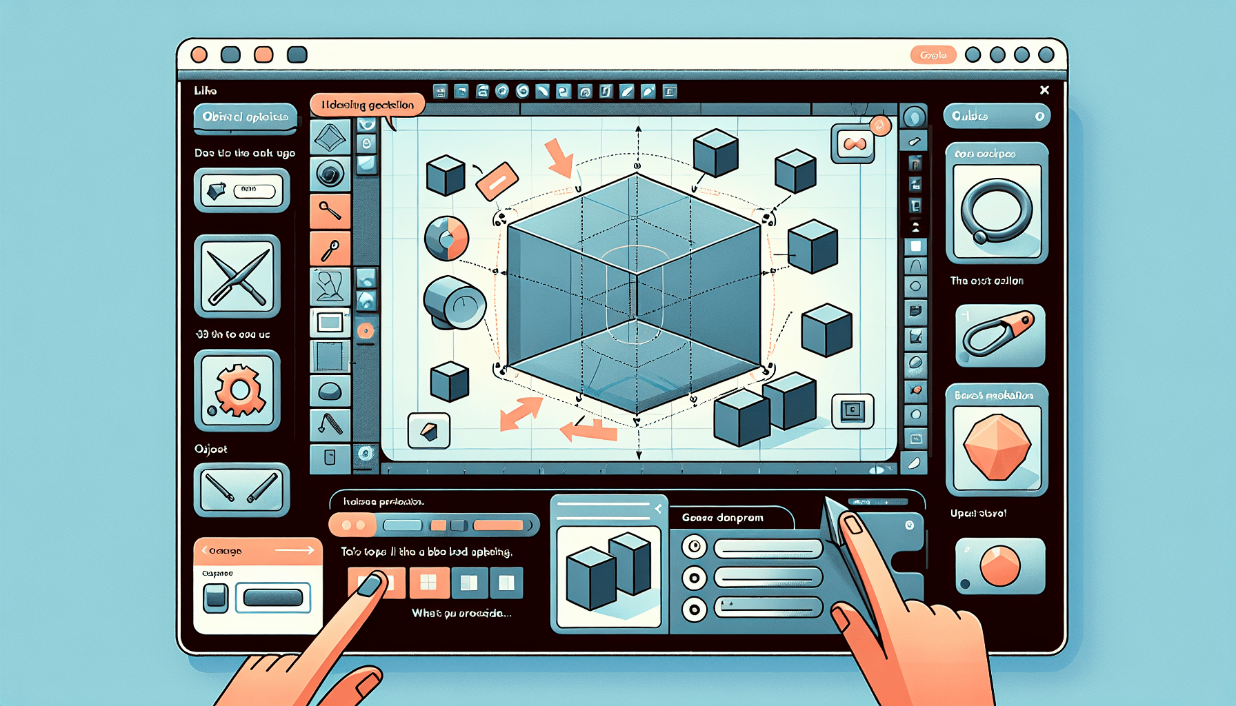
Blender is a powerful 3D modeling software that offers a wide range of tools and features. Before diving into creating a 3D model of a hammer, it is important to understand the basics of Blender. This section will cover essential functions such as zooming, panning, selecting objects, moving, scaling, and rotating.
Zooming
In Blender, there are multiple ways to zoom in or out of the viewport. One way is to click and hold the left mouse button on the magnifier icon and move the mouse. Another method is to use the scroll wheel on the mouse to zoom in or out. Additionally, you can use hotkeys such as pressing “1” on the number pad to switch to front view.
Panning
To pan the view in Blender, hold down the shift key and press the middle mouse button while moving the mouse. This allows you to navigate around the scene without changing the zoom level. Panning is useful when working with larger models or when you need to focus on a specific area of the scene.
Selecting objects
Selecting objects in Blender is straightforward. Simply left-click on an object to select it. By holding down the left mouse button and dragging, you can also use the selection box to select multiple objects at once. To deselect everything, either press “Alt + A” or click anywhere outside of the objects.
Moving
Once an object is selected, you can move it by pressing “G” on the keyboard and then moving the mouse. The object will follow the movement of the mouse cursor. To restrict the movement to a specific axis, press “X” for the x-axis, “Y” for the y-axis, or “Z” for the z-axis. If you want to move the object by a specific distance, you can type in the numeric value.
Scaling
Scaling an object in Blender allows you to make it larger or smaller. To scale an object, select it and press “S” on the keyboard. Then, move the mouse to adjust the size. Similar to moving, you can restrict the scaling to a specific axis by pressing “X,” “Y,” or “Z.” Typing in a numeric value also allows you to scale the object by a specific amount.
Rotating
Rotating an object in Blender can be done by selecting it and pressing “R” on the keyboard. By moving the mouse, you can rotate the object around the 3D space. Like moving and scaling, restricting the rotation to a specific axis is possible by pressing “X,” “Y,” or “Z.” Numeric values can also be entered to rotate the object by a specific angle.
These basic functions are essential for navigating and manipulating objects in Blender. Understanding how to zoom, pan, select, move, scale, and rotate objects will greatly enhance your modeling experience.
Starting the 3D Model
Once you are familiar with the basics of Blender, you can begin creating your 3D model of a hammer. This section will guide you through the initial steps of modeling the hammer head.
Extruding
To start modeling the hammer head, you will need a base shape. In Blender, you can create a basic shape by starting with a cube. Switch to edit mode by pressing the “Tab” key on the keyboard. In edit mode, you can manipulate the vertices, edges, and faces of the object.
To create the base shape, select the face select mode by clicking the “Face Select” button. Click on the face of the cube that you want to extrude. Once you have selected the desired face, press the “E” key on the keyboard to extrude it. Move the new face slightly to the left to give it the shape of the hammer head.
Scaling
After extruding the face, you can scale it down in size to refine the shape. Press the “S” key on the keyboard to activate the scaling tool. Move the mouse to adjust the size of the face. You can refer to the numeric value displayed to precisely control the scale. Left-click to complete the scaling operation.
Adding loop cuts
To add more geometry and refine the shape of the hammer head, you can use loop cuts. Loop cuts are a way to add additional edges to a mesh. Press “Ctrl + R” to add a loop cut. Use the scroll wheel to determine the number of cuts you want to add, in this case, two cuts. Left-click to confirm the position of the cuts and right-click to center them.
By adding loop cuts, you create more vertices and edges, allowing for greater control over the shape of the model. Loop cuts are particularly useful when you need to add detail or define sharp edges.
Transforming shapes
Blender offers various tools to transform shapes and achieve desired results. To transform the cube shape into a sphere shape, you can use the “To Sphere” tool. Select the face that you want to transform, go to the “Mesh” menu, choose “Transform,” and then select “To Sphere.”
Enter a value, such as 1, to adjust the strength of the transformation. The shape will deform accordingly, giving you a sphere-like structure. This technique can be useful when you need to manipulate shapes to match specific design requirements.
Using subdivision surface modifiers
To create a smoother surface for the hammer head, you can apply a subdivision surface modifier. Switch to object mode by pressing the “Tab” key and go to the modifiers panel. Click on the “+ Add Modifier” button and choose “Subdivision Surface.”
Adjust the number of subdivisions for the viewport and the final render. Increasing the number of subdivisions will make the surface smoother. The subdivision surface modifier is a non-destructive tool that can enhance the appearance of your model without altering the base geometry.
By following these steps, you have successfully started the 3D model of the hammer head. The extrusion, scaling, loop cuts, shape transformation, and subdivision surface modifiers have laid the foundation for creating a detailed and realistic hammer head.
Find 3D Printing Accessories Here
Creating the Hammer Head
Now that you have established the base shape of the hammer head, you can focus on refining it and adding details. This section will guide you through the process of modeling the hammer head.
Modeling the basic shape
With the base shape prepared, you can now refine it further. Use techniques such as extrusion, scaling, and transformation to manipulate the vertices, edges, and faces to achieve the desired shape. Modeling the basic shape requires creativity and attention to detail.
Refining the hammer head
By adding additional loop cuts, you can refine and shape the hammer head. Loop cuts allow for more precise control over the surface and can help define the shape of various components of the model. Experiment with different loop cuts to find the best way to refine the hammer head.
Adding details
To make the hammer head look more realistic, consider adding details such as grooves or indentations. Extrude faces or edges to create extra geometry and then manipulate them to achieve the desired effect. Small details can add depth and interest to your model.
Creating the face of the hammer
The face of the hammer is an important feature that can greatly impact the overall appearance of the model. Use extrusion, scaling, and loop cuts to create the face of the hammer. Pay attention to proportions and symmetry to ensure an accurate and visually appealing result.
By following these steps, you can create an accurate and detailed 3D model of the hammer head. The modeling process requires patience, creativity, and attention to detail, but the end result is a well-modeled and realistic hammer head.
Creating the Handle
Once you have completed the hammer head, it’s time to move on to creating the handle. The handle is an essential component of the hammer and requires careful modeling to ensure the right shape and proportions.
Adding a cylinder for the handle
To start modeling the handle, add a cylinder object to the scene. Switch to object mode by pressing the “Tab” key and go to the “Add” menu. Choose “Mesh” and then “Cylinder.” Adjust the parameters of the cylinder, such as the number of vertices, to match the desired size and shape of the handle.
Reshaping the handle
After adding the cylinder, you can reshape it to resemble the handle of a hammer. Use techniques such as scaling, extruding, and transforming shapes to achieve the desired result. Pay attention to proportions and reference images to create an accurate representation of a hammer handle.
Adding loop cuts for grip
To create a grip texture on the handle, you can add loop cuts. Switch to edit mode by pressing the “Tab” key and add loop cuts to the handle using the “Ctrl + R” shortcut. Adjust the number and position of the loop cuts to create the desired grip texture. This step adds more geometry to the handle, allowing for greater realism and detail.
Creating a grip texture
To enhance the grip texture further, consider using techniques such as sculpting or adding surface details. Blender offers various tools to add texture and detail to objects. Experiment with different brushes and effects to achieve the desired grip texture.
By following these steps, you can create a realistic and detailed handle for the hammer. The addition of loop cuts and the creation of a grip texture add authenticity and visual interest to the model.

Smoothing the Surface
To make the hammer model look more polished and refined, you can smooth the surface. This section will guide you through the process of smoothing the surface of both the hammer head and the handle.
Applying subdivision surface modifier
To smooth the surface, you can apply a subdivision surface modifier. This modifier increases the number of subdivisions, resulting in a smoother appearance. Switch to object mode by pressing the “Tab” key, go to the modifiers panel, and add a subdivision surface modifier. Adjust the number of subdivisions for both the viewport and the final render.
Adjusting the subdivisions
The level of subdivisions determines the level of smoothness. Experiment with different subdivision levels to find the desired balance between detail and performance. Keep in mind that higher subdivision levels may require additional processing power and can impact the performance of your model.
Smoothing out the handle
Use techniques such as sculpting or smoothing brushes to further refine the surface of the handle. Blender offers various tools to smooth out rough surfaces and achieve a more polished appearance. Pay attention to details and ensure that the handle is consistent with the desired aesthetics.
Refining the hammer head
Apply the same smoothing techniques to the hammer head to create a more rounded and polished look. Detailed and accurate modeling combined with proper smoothing techniques can greatly enhance the overall appearance of the hammer model.
By smoothing the surface of the hammer model, you can achieve a more realistic and visually appealing result. The application of subdivision surface modifiers and the use of smoothing brushes ensure that the surfaces are refined and polished.
Adding Sharp Edges
While smoothing the surface of the hammer model is important, certain areas may require sharp edges for added realism. This section will guide you through the process of adding sharp edges to the hammer head.
Adding loop cuts to the hammer head
To create sharp edges, you can add loop cuts to the hammer head. Switch to edit mode by pressing the “Tab” key and use the “Ctrl + R” shortcut to add loop cuts. Position the loop cuts near the edges that you want to sharpen. By introducing more geometry, you can control the sharpness of the edges.
Defining the sharp edges
After adding the loop cuts, you can define the sharp edges further. Select the edges that you want to sharpen by holding the “Alt” key and left-clicking on the desired edges. With the edges selected, use the scaling tool (“S” key) to scale them down to zero on the y-axis. This action flattens the edges, resulting in a sharper appearance.
Fine-tuning the edge flow
To ensure the sharp edges flow smoothly and naturally, you may need to adjust the geometry further. Select adjacent faces or edges and use tools such as scaling or moving to align them properly. The goal is to create a visually appealing and realistic transition between the sharp edges and the rest of the model.
By adding sharp edges to the hammer head, you can achieve a higher level of detail and realism. The careful placement of loop cuts and the definition of sharp edges ensure that the model accurately represents the shape and structure of a real hammer.
Finalizing the 3D Model
Once you have completed the modeling process, it is important to review the 3D model and make any necessary adjustments. This section will guide you through the final steps of finalizing the 3D model of the hammer.
Checking for imperfections
Thoroughly inspect the 3D model for any imperfections, such as intersecting geometry or uneven surfaces. Check the overall shape, proportions, and the alignment of various components. Zoom in and examine the model from different angles to ensure that it meets your expectations.
Making necessary adjustments
If you identify any imperfections or areas that require further refinement, make the necessary adjustments. Use tools such as sculpting, scaling, or transforming shapes to correct any issues. Attention to detail and careful adjustments will contribute to the overall quality of the 3D model.
Reviewing the overall shape
Take a step back and review the overall shape of the hammer model. Does it match your initial vision? Are there any inconsistencies or areas that need improvement? Compare the model to reference images or real-life hammers to ensure accuracy and realism.
Ensuring proper geometry
Verify that the geometry of the 3D model is correct and optimized. Avoid unnecessary vertex density or complex shapes that may hinder the performance of the model. Ensure that the mesh is clean and follows best practices for efficient rendering and animation.
By completing these final steps, you can ensure that the 3D model of the hammer is accurate, realistic, and visually appealing. Thoroughly reviewing and making necessary adjustments will elevate the quality of the final product.
Conclusion
In this tutorial, we have covered the basics of Blender and demonstrated various functions such as zooming, panning, selecting objects, moving, scaling, and rotating. By mastering these fundamental techniques, you can navigate and manipulate objects in Blender effectively.
We have also explored the process of creating a 3D model of a hammer. From starting the model by extruding and scaling to refining the hammer head through loop cuts and shape transformations, we have provided detailed steps for achieving a realistic result.
Additionally, we have discussed the creation of the handle, the smoothing of the surface, the addition of sharp edges, and the finalization of the 3D model. These stages ensure that the model is accurate, polished, and ready for further enhancements such as adding materials and textures.
In the next video tutorial, we will demonstrate how to add materials and textures to the hammer model. This will further enhance its appearance and bring the model to life. By following this comprehensive tutorial, you have gained a solid foundation in 3D modeling using Blender 2.8.
Maintain Your 3D Printer with these Tools


