FLASHFORGE Adventurer 5M 3D Printer with Fully Auto Leveling, Max 600mm/s High Speed Printing, 280°C Direct Extruder with 3S Detachable Nozzle, Core XY All Metal Structure, Print Size 220x220x220mm
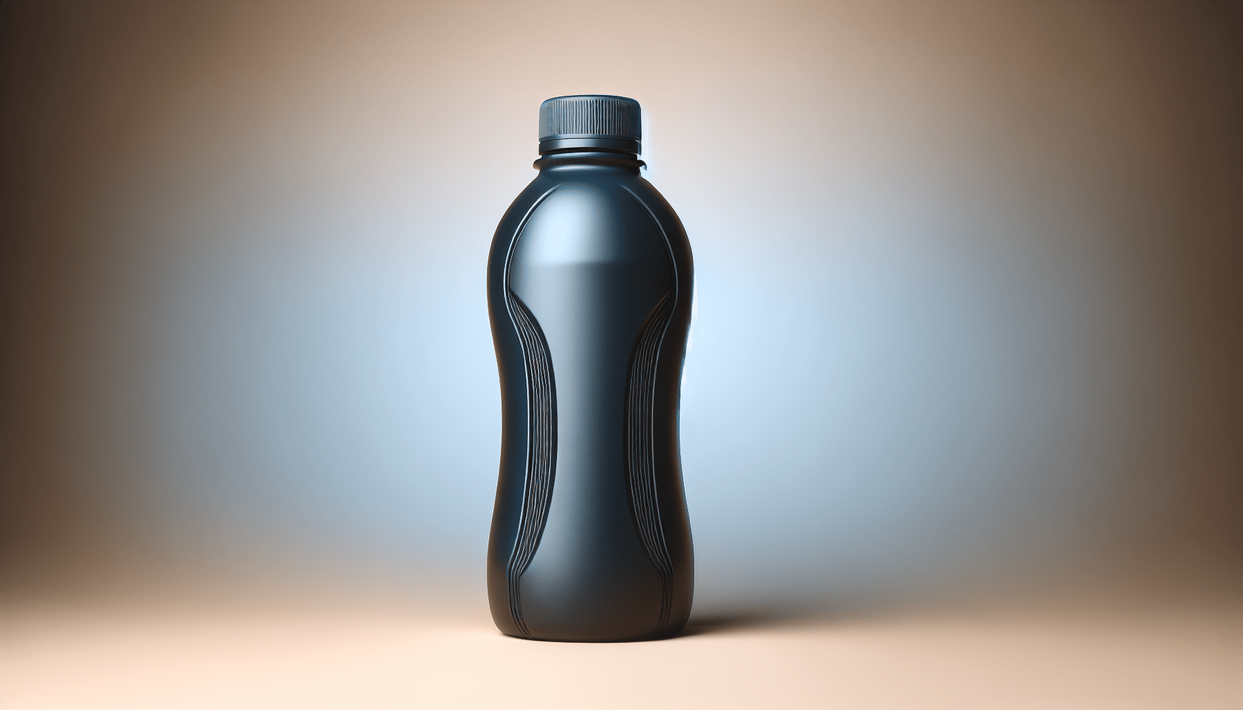
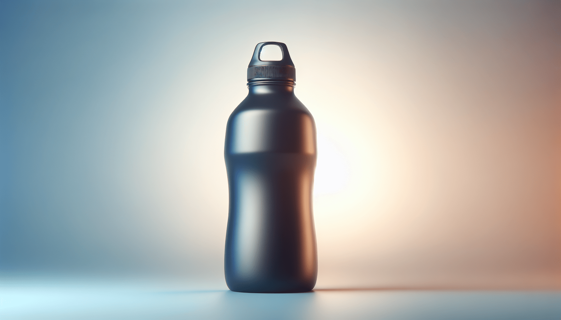
$259.00 (as of June 18, 2025 23:32 GMT +00:00 - More infoProduct prices and availability are accurate as of the date/time indicated and are subject to change. Any price and availability information displayed on [relevant Amazon Site(s), as applicable] at the time of purchase will apply to the purchase of this product.)In this comprehensive guide titled “Blender 3D Modeling Tutorial: How To Model a Sport Bottle,” you will be provided with a meticulous walkthrough of creating a 3D sport bottle using Blender 4.1.1. The tutorial specifically caters to beginners, ensuring that every step is clearly explained, from the initial deletion of the default cube to the application of intricate material effects. Detailed instructions on essential operations such as adding mesh circles, configuring vertices, and employing various commands like extrude, scale, and snap modes are included to enhance your modeling skills.
Furthermore, the guide covers more advanced techniques like edge manipulation, beveling, and the use of modifiers such as subdivision and solidify. You will also learn to shape different components of the bottle, set up the environment and lighting, and adjust materials for rendering. Practical tips are provided throughout to streamline the modeling process and ensure precision in your final product. By following the steps outlined in this tutorial, you will gain a comprehensive understanding of 3D modeling in Blender, culminating in a professionally rendered sport bottle.
Deleting the Default Cube
Open Blender and locate the default cube.
When you first open Blender, you will be greeted with a default scene that includes a cube, a camera, and a light. The default cube is typically highlighted in orange, indicating that it is currently selected. This default cube may be familiar to you if you have worked with Blender before. Understanding how to manipulate this initial scene is crucial for starting any new project.
Press the ‘X’ key to delete the default cube.
To begin your modeling project, you need to clear the default scene. Simply press the ‘X’ key on your keyboard while the cube is selected. A pop-up menu will appear, asking for confirmation to delete the selected object. Click ‘Delete’ or press ‘Enter’. This action removes the cube, leaving you with a clean workspace for your new model. This fundamental step ensures that there are no unnecessary elements in your scene as you proceed with your modeling tasks.
Setting Up the Initial Mesh
Add a mesh circle by pressing ‘Shift + A’.
With the default cube deleted, you can now start adding new elements to your scene. To add a new mesh, press ‘Shift + A’ to open the Add menu. From this menu, navigate to ‘Mesh’ and then select ‘Circle’. This action will place a new circular mesh at the center of your scene. Circles are useful starting shapes for round objects and provide a good foundation upon which to build your model.
Configure the number of vertices in the bottom left corner.
Upon adding the circle, look at the bottom left corner of the screen. Here, you will see options to adjust the properties of the circle, such as the number of vertices. By default, the circle might have 32 vertices, but for this tutorial, set the number of vertices to 16. A lower number of vertices will simplify the model and make it easier to manage, especially for beginners. Adjusting these properties is an essential part of initializing your mesh to match the desired complexity and detail of your final model.
Find 3D Printing Accessories Here
Extruding and Scaling Vertices
Switch to Edit Mode by pressing ‘Tab’.
To begin transforming your circle into more complex shapes, you need to switch from Object Mode to Edit Mode. Press the ‘Tab’ key, which toggles between these modes. In Edit Mode, you can manipulate the vertices, edges, and faces of your mesh, which is crucial for precise modeling tasks.
Select the circle and use the ‘E’ key to extrude vertices.
In Edit Mode, ensure that all vertices of the circle are selected. You can do this quickly by pressing ‘A’. Next, to extrude the vertices, press the ‘E’ key. Extrusion allows you to extend your mesh along a specific axis. When you press ‘E’, drag the mouse or type coordinates to define the extrusion’s direction and distance. In this case, extrude along the Z-axis by typing ‘E’, then ‘Z’, and then entering a value like ‘0.8’.
Scale the extruded vertices using the ‘S’ key.
After extruding the vertices, you may want to scale them to modify the shape of your model. With the extruded vertices still selected, press the ‘S’ key to scale them. For example, to create a wider base, drag outward with the mouse or enter a scaling factor numerically. For precision, you might type ‘S’ followed by ‘7’ to scale them sevenfold. Repeating the extrusion and scaling processes allows you to build up your model progressively, adjusting the shape as needed.
Adding and Adjusting Loop Cuts
Add loop cuts by pressing ‘Ctrl + R’.
Loop cuts are essential tools for adding geometry to your model, allowing you to refine its shape. Press ‘Ctrl + R’ to activate the loop cut tool. A preview of the cut, represented by a purple line, will appear on your mesh. This tool allows you to add new edge loops, which can be positioned to control the density of your mesh in specific areas.
Use the mouse to position the loop cuts and click to confirm.
Once the loop cut tool is active, move the mouse to position the loop cut where you need it. For instance, to place it at a specific height along a cylindrical form, use the visual feedback provided. Click the left mouse button to confirm the initial position of the loop cut.
Adjust the placement of loop cuts to define the shape.
After confirming the initial placement, you can slide the loop cut along the surface by moving the mouse. Click again to finalize its position. Properly positioned loop cuts will help define the contours and structural details of your model. Adjust loop cuts to create features such as ridges, contours, and other intricate details required for a realistic and functional bottle model.
Modeling the Bottle Components
Model the bottom part by adjusting the vertices.
Start by focusing on the bottom part of the bottle. Using the vertices, edges, and faces, adjust the bottom area to create a stable base. This might involve extruding outwards to create a broader foundation or scaling vertices inward to form a concave bottom. This step ensures that your bottle has a realistic bottom that can support its structure.
Extrude and scale to form the body of the bottle.
Move up from the bottom part by selecting the edge loop at the top and extruding it upwards using the ‘E’ key. Scale the vertices appropriately to shape the body of the bottle. Continue this process incrementally, extruding and scaling, to form the cylindrical body and the gradual taper towards the neck of the bottle. This process allows you to create the elongated and smooth body characteristic of most sport bottles.
Create the neck and mouth of the bottle using further extrusions.
Finally, model the neck and mouth by continuing the extrusion and scaling process. The neck typically involves reducing the diameter significantly compared to the bottle’s body. Extrude upwards with smaller scales until you reach the desired height. For the mouth, perform another extrusion and scale it outwards to form the bottle’s opening. Proper attention to the neck and mouth ensures a practical design where a cap can be fitted.
Switching Between Modes
Switch to Face Select Mode by pressing ‘3’.
To handle different aspects of your model, you can switch between various selection modes. Press the ‘3’ key to enter Face Select Mode. This mode allows you to select and manipulate faces of the mesh rather than individual vertices or edges.
Select faces by holding the shift key.
In Face Select Mode, you can select multiple faces by holding down the Shift key while clicking. This multi-selection method is useful for uniformly adjusting a group of faces, for instance, extruding multiple faces to create features like handles or design patterns.
Switch between wireframe and solid view with the ‘Z’ key.
To get a different perspective on your work, press the ‘Z’ key to toggle between wireframe view and solid view. Wireframe view allows you to see and select hidden geometry, which is beneficial when working on intricate internal parts. Alternately, solid view gives a realistic representation of the model’s surface, aiding in visualizing the final product.
Using Edge Menu and Bevels
Select edges and use the Edge Menu for Bridge Edge Loops.
In certain sections, such as creating handles or joining separate parts of the model, you may use the ‘Edge’ menu. Select the edges you wish to connect, and then navigate to the Edge menu and select ‘Bridge Edge Loops’. This operation creates faces between the selected edge loops, effectively merging them and shaping the structure.
Apply a flat bevel to edges for smooth transitions.
Bevels are crucial for smoothing transitions and refining edges. Select the edges you want to bevel and press ‘Ctrl + B’ to activate the bevel tool. Drag the mouse to adjust the bevel’s width and add more segments for a smoother curve. A flat bevel can make edges appear more natural and less jagged.
Modify bevel settings for desired sharpness.
After applying a bevel, you can adjust its properties in the tool menu appearing at the lower-left corner. Increase the number of segments to produce a finer curve or adjust the profile to control the sharpness. Using these settings allows you to achieve the desired aesthetic and functional properties of your model.
Vertex and Edge Refinements
Select and scale vertices to create rectangular areas.
For certain designs, you may need to create rectangular or other specific areas. In Vertex Select Mode, select the relevant vertices and uniformly scale them on one axis using the ‘S’ key followed by the appropriate axis key (‘X’, ‘Y’, or ‘Z’). This technique helps in defining flat or rectangular regions on the model.
Extrude, scale, and move vertices to refine geometry.
Refining the geometry involves continuous adjustments. Extrude vertices where you need new geometry, such as additional thickness or detail. Scale and move these vertices to precisely position the new elements. This iterative process is vital for refining the shape, ensuring the design meets your specifications.
Applying Subdivision and Solidify Modifiers
Add a Subdivision Surface modifier to smooth surfaces.
To give the model a smooth, polished look, apply a Subdivision Surface modifier. In Object Mode, select your model and go to the Modifiers panel. Choose ‘Subdivision Surface’ from the list. This modifier increases the mesh’s complexity by adding more geometry and smoothing surfaces, making the object appear more refined.
Insert loop cuts to define sharp edges.
However, the Subdivision Surface modifier can sometimes overly smooth out certain features. To maintain sharp edges and critical details, insert additional loop cuts near these areas. Press ‘Ctrl + R’ and place loop cuts close to the edges you wish to keep sharp. This technique is called edge sharpening and ensures important features remain distinct.
Apply the Solidify modifier to give the model thickness.
For objects like a bottle that requires a perceptible thickness, the Solidify modifier is essential. Again, in the Modifiers panel, select ‘Solidify’. Adjust the thickness parameter to your preference, giving the bottle a realistic wall thickness. Positioning this modifier correctly in the stack is critical to ensure other modifiers like Subdivision Surface are applied appropriately.
Conclusion
Review the final model and render.
After completing the modeling process, review the final product thoroughly. Inspect it from various angles and in different modes (solid and wireframe) to ensure there are no defects or inconsistencies. Make minor adjustments as necessary to perfect the model.
Discuss potential next steps or additional features to explore.
Upon completing and reviewing your sport bottle model, you might consider adding more details like textures and materials. Using Blender’s powerful rendering capabilities, set up lighting and environment to create realistic renders of your model. Explore further features like animation, simulation of fluids to visualize the bottle in use, or creating promotional visuals. Additionally, understanding how to 3D print the model or export it for use in game engines could be valuable next steps, expanding the practical applications of your work.
Maintain Your 3D Printer with these Tools


