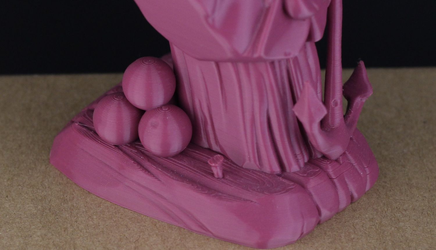
FLASHFORGE Adventurer 5M 3D Printer with Fully Auto Leveling, Max 600mm/s High Speed Printing, 280°C Direct Extruder with 3S Detachable Nozzle, Core XY All Metal Structure, Print Size 220x220x220mm
$259.00 (as of June 19, 2025 23:45 GMT +00:00 - More infoProduct prices and availability are accurate as of the date/time indicated and are subject to change. Any price and availability information displayed on [relevant Amazon Site(s), as applicable] at the time of purchase will apply to the purchase of this product.)In the exploration of designing buckles, clips, and snaps for 3D printing, you are presented with a comprehensive tutorial by Maker’s Muse. This guide encapsulates a full spectrum of the design process, ranging from initial research and inspiration to the final stages of 3D printing. The video meticulously covers each phase, including conceptualization and detailed CAD design using Fusion 360, alongside practical tips on slicing and printing using PrusaSlicer 2.0. Emphasis is placed on understanding traditional joining methods and how the integration of locking mechanisms within 3D-printed models can eliminate the necessity of additional hardware.
Focusing on everyday items like waterproof cases and pen boxes, the video provides in-depth examples to illustrate various locking designs suited for different purposes. Whether you require designs intended for regular access or permanent locking, Maker’s Muse offers clear guidance through practical examples. Additionally, key considerations such as material elasticity and appropriate clearances are discussed, ensuring robust and functional designs. By the end of this tutorial, you will be well-equipped to design and print sophisticated locking mechanisms, fostering both creativity and technical proficiency in 3D printing.
Research Phase
Purpose and Utility of the Mechanisms
Understanding the purpose and utility of buckles, clips, and snaps is fundamental in designing effective 3D-printed locking mechanisms. Such components provide an essential means to join parts either temporarily or permanently. They are engineered to offer ease of assembly and disassembly while maintaining mechanical integrity and reliability. Through the proper design of these mechanisms, you eliminate the need for additional hardware, reducing weight and cost, and streamlining manufacturing processes. Additionally, these elements ensure that products function as intended, offering secure closures and facilitating repeated use.
Analysis of Existing Buckles, Clips, and Snaps
To create innovative designs, an in-depth analysis of current buckles, clips, and snaps is crucial. Reviewing everyday items such as waterproof cases, packaging, and fastening devices reveals a wealth of inspiration and mechanical strategies. For example, a waterproof case usually employs clips with tight engagement and robust construction to prevent water ingress, whereas a pen box might utilize light and easily removable snaps. By dissecting these existing designs, you gain insights into how different forces, shapes, and materials interact, pinpointing successful attributes that can be adapted and improved upon.
Material Properties and Considerations
Material properties play a pivotal role in designing effective 3D-printed mechanisms. Common materials like PLA, ABS, PETG, and flexible filaments each have distinct characteristics, impacting the resilience, flexibility, and durability of the final product. PLA, for instance, is easy to print and stiff but may be brittle; in contrast, TPU offers high flexibility and impact resistance, which are beneficial for components needing frequent deformation. Understanding these properties enables meticulous selection and application, ensuring that the design withstands expected mechanical forces and environmental conditions.
Case Studies of Successful 3D Printed Designs
Case studies of successful 3D-printed designs showcase practical applications and their efficiency. Studying designs like Enclosure Snap Fits, Reusable Cable Ties, and Modular Clips offers real-world examples of how innovative geometry and material selection result in functional products. These case studies highlight the iterative process of prototyping, testing, and refining. They provide invaluable lessons on dealing with issues such as warping, insufficient strength, or poor fit, guiding you towards achieving optimal designs.
Conceptualization
Identifying User Requirements and Use Cases
The initial step in conceptualization is identifying user requirements and specific use cases. Understand who will use the product, how they will interact with it, and the environmental conditions it will face. Requirements may include ease of use, load-bearing capacity, durability, and specific aesthetic qualities. Use cases might range from a simple snap-fit for packaging to a robust buckle for a hiking backpack. Clearly defining these criteria ensures that your designs meet the practical needs of users.
Sketching Initial Ideas and Concepts
Sketching serves as a visual brainstorming tool where initial ideas and concepts come to life. Begin with rough sketches to explore potential shapes, engagement mechanisms, and assembly methods. Focus on the functional aspects like how the parts will interact and how forces will be distributed. This stage is crucial for visualizing the mechanics and progressing towards more detailed designs. Rough sketches also facilitate sharing ideas with stakeholders for early feedback.
Considering Mechanical Forces and Durability
When moving from sketches to detailed designs, consider the mechanical forces and durability of each element. Analyze the loading conditions, such as tensile, compressive, and shear forces that the mechanism will encounter. Utilize FEA (Finite Element Analysis) tools if available to predict how the design will perform under stress. Design tweaks like adding fillets, ribs, and varying thickness can drastically improve durability and functionality.
Iteration and Refinement of Designs
Design is an iterative process. Create prototypes and test them rigorously. Identify points of failure, weaknesses, or areas for improvement through physical and virtual testing. Iterations may involve redesigning shapes, adjusting dimensions, or experimenting with different materials. Refinement is essential to evolve a concept from a theoretical sketch to a practical, reliable, and efficient design.
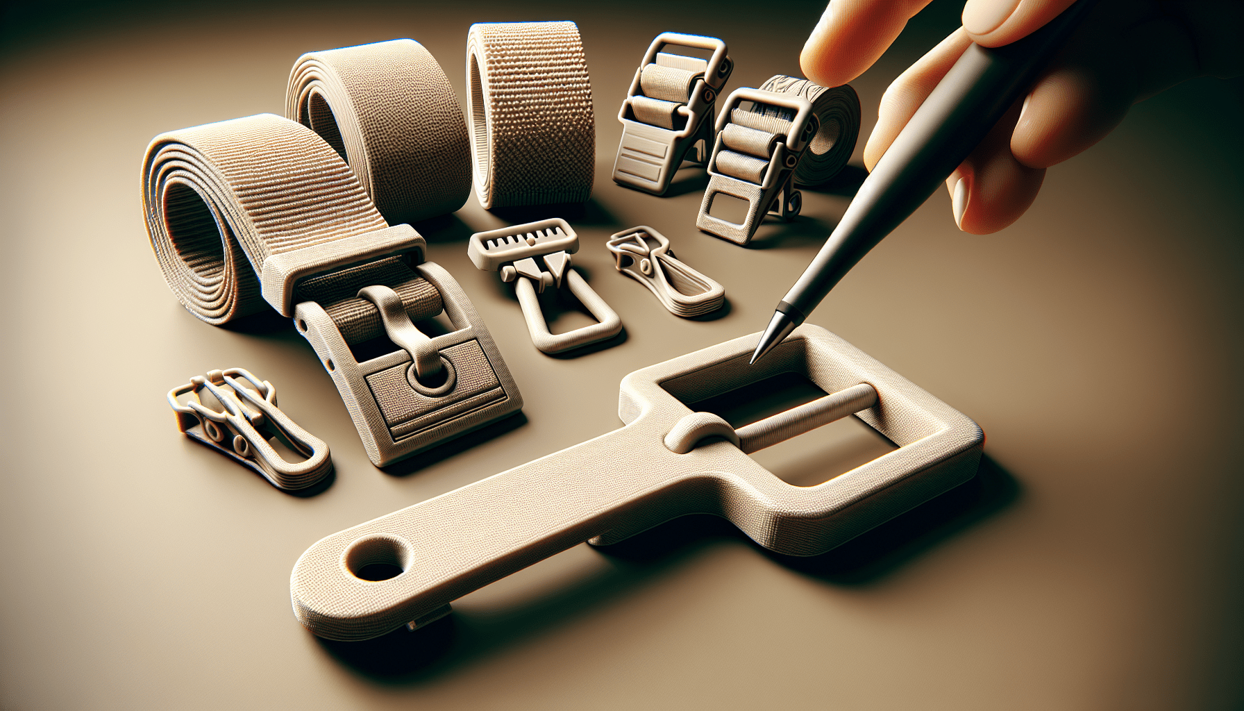
Find 3D Printing Accessories Here
CAD Design using Fusion 360
Introduction to Fusion 360
Fusion 360 is a comprehensive CAD tool widely used for designing 3D models. It offers a powerful suite of features for creating, assembling, and simulating components. As a cloud-based platform, it allows for collaborative design and iteration. Its integration of modeling, sculpting, and parametric design capabilities makes it a preferred choice for creating intricate and functional mechanical parts.
Setting Up the Workspace
Before diving into your design, setting up the workspace in Fusion 360 is essential. Establish the correct units and dimensions based on your design specifications. Organize the interface by customizing toolbars for quick access to frequently used features. Categorize components in folders for easier management, especially in complex assemblies.
Creating Basic Shapes and Forms
Begin by constructing basic shapes and forms that constitute the foundation of your designs. Utilize sketches to draw profiles, then use extrusion, revolve, sweep, and loft features to convert these profiles into 3D solids. This step is fundamental in developing the primary form and structure of your mechanisms.
Incorporating Mechanical Features (Ramps, Ledges, etc.)
Next, integrate mechanical features such as ramps, ledges, and snaps into your design. These features are critical in achieving the desired locking and engagement behaviors. Utilize sketch constraints and parametric dimensions to ensure accurate and adaptable design elements. Fusion 360’s advanced sketching and modeling tools enable the precise crafting of these intricate details.
Assembling Parts in 3D Space
As the individual components are developed, proceed to assemble them in the 3D space within Fusion 360. Use constraints to accurately position and align parts. This step is crucial for visualizing the interactions between different components and ensuring they fit together seamlessly. Simulate movements and test the assembly for any interference or misalignments.
Finalizing the Design
Finalize the design by addressing any issues identified during the assembly phase. Make necessary adjustments to ensure all parts interact correctly and refine the design for better performance and aesthetics. Verify dimensions and ensure all features are precisely defined, aiding in a smoother transition to the printing phase.
Slicing for 3D Printing using PrusaSlicer
Importing CAD Models into PrusaSlicer
Once the design is finalized, export the CAD models and import them into PrusaSlicer. PrusaSlicer supports various file formats like STL and OBJ, compatible with most 3D printing software. Upon import, inspect the model to ensure it is correctly oriented and scaled.
Adjusting Print Settings for Optimal Results
Adjust the print settings to optimize for quality, strength, and speed. Layer height, print speed, and temperature settings are crucial parameters. The choice of filament and printer capabilities will guide these adjustments. PrusaSlicer offers profiles for different filaments and printers, simplifying this process.
Configuring Layer Height, Infill Density, and Supports
Configure layer height, infill density, and supports according to the design’s requirements. A finer layer height improves detail but increases print time. Select an infill pattern and density that balances weight and structural strength. Add supports where necessary to ensure overhangs and complex geometries print successfully.
Previewing and Analyzing the Print Path
Use PrusaSlicer’s preview function to analyze the print path visually. This step is essential to identify potential issues such as insufficient support, weak points, or excessive print time. Adjust settings as needed based on this analysis.
Exporting G-Code for Printing
Once satisfied with the print settings and path analysis, export the G-code file. The G-code contains all instructions for the 3D printer, including movements, extrusion amounts, and speeds. Ensure the G-code is compatible with your specific 3D printer model.
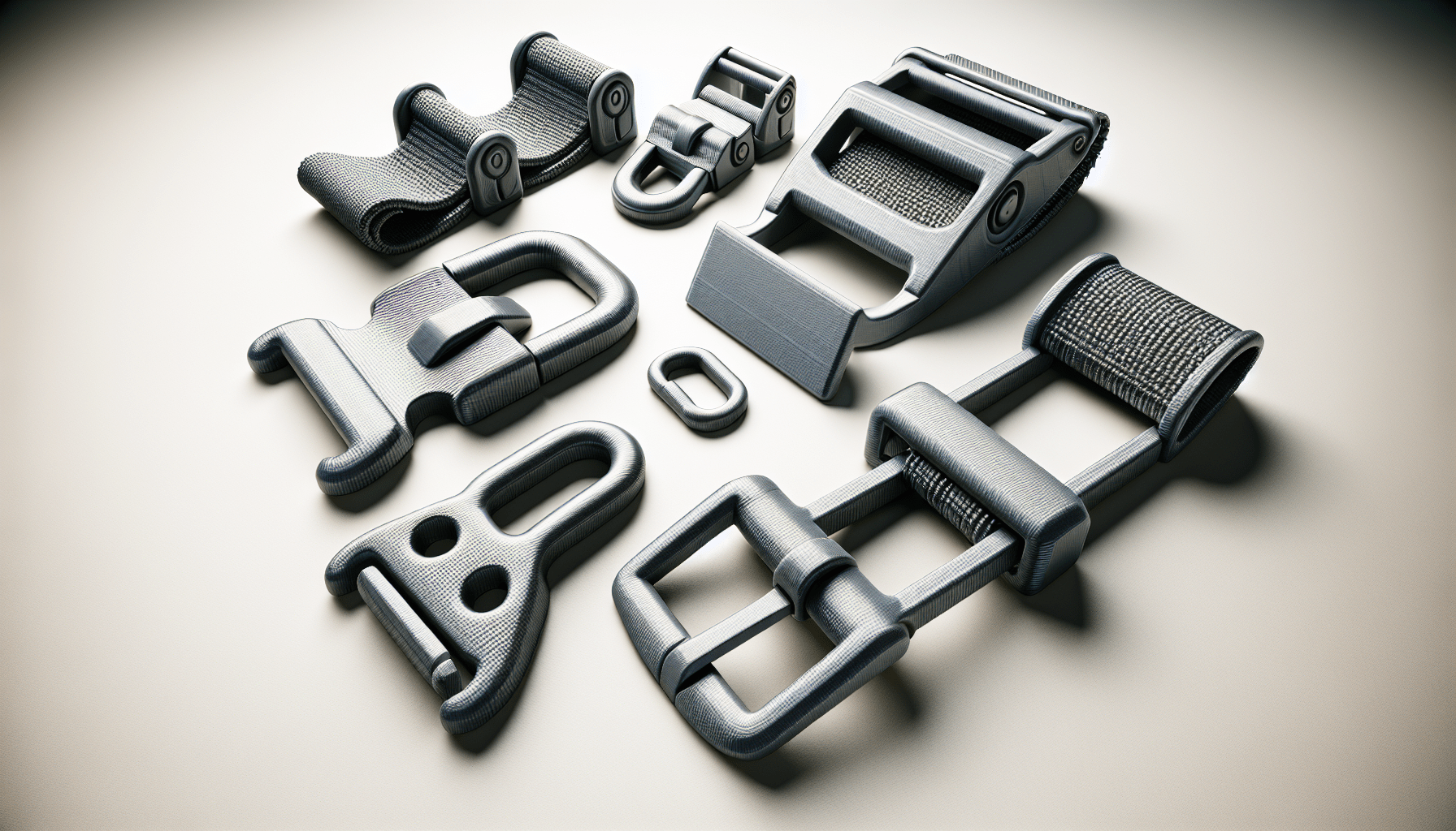
3D Printing Process
Printer Setup and Calibration
Proper printer setup and calibration are vital for achieving high-quality prints. Start by leveling the print bed and ensuring the nozzle is clean and at the correct height. Regular calibration routines, such as printing a test cube, can verify the printer’s accuracy and consistency.
Selecting the Right Filament
Choose the filament that best suits the design’s mechanical requirements. For flexible parts like snaps and clips, TPU might be appropriate. For more rigid and strong components, consider filaments like PETG or glass-filled nylon.
Loading the Filament and Initializing the Print
Load the filament into the printer, ensuring it feeds correctly without tangles. Initialize the print by warming up the bed and nozzle to the appropriate temperatures, guided by the filament specifications. Start the print process, ensuring all settings are correctly applied.
Monitoring Print Progress
Closely monitor the print progress, especially during the initial layers to ensure proper adhesion. Regular checks can identify issues such as warping, layer misalignment, or filament jams early, allowing for timely intervention to avoid failed prints.
Troubleshooting Common Issues
Address common issues such as poor bed adhesion, stringing, and layer delamination promptly. Solutions might include adjusting the bed temperature, re-calibrating the nozzle height, or slowing down print speeds. Regular monitoring and adjustments help maintain print quality and reliability.
Evaluating the Printed Results
Inspecting for Print Quality and Defects
After printing, inspect the part thoroughly for any defects or quality issues. Check surface finish, layer bonding, and dimensional accuracy. Tiny defects can significantly impact the functionality of intricate mechanical parts.
Testing the Mechanical Integrity of the Design
Test the mechanical integrity of the design by applying forces and movements the components will experience in use. Evaluate if the parts meet the intended strength, flexibility, and functionality criteria. This testing phase is vital in determining if further design iterations are necessary.
Performing Fit and Function Tests
Assemble the printed parts and perform fit and function tests. Assess if the components interact as designed and if the locking mechanisms work seamlessly. This stage verifies that the parts fit together without excessive force and function correctly under expected use.
Documenting Observations and Improvements
Document all observations and identified areas for improvement. Detailed notes help in refining the design and optimizing future iterations. Record parameters like print settings, material choice, and testing results to track progress and knowledge gain.
Designing for Deformation and Elasticity
Understanding Material Deformation
Designing flexible elements requires a solid understanding of material deformation. Materials like TPU exhibit high elasticity, which can be leveraged in designs that require deformation for engagement and disengagement. Properly accounting for material deformation ensures longevity and functionality.
Incorporating Flexible Elements
Incorporate flexible elements like living hinges and deformable snaps into your designs. These elements rely on precise geometry that allows for bending or stretching without breaking. Thoughtful design and material selection are key to achieving the desired elasticity.
Calculating Appropriate Clearances
Clearances are crucial in ensuring parts move and engage properly. Calculate appropriate clearances that account for material tolerance and printer accuracy. Tight tolerances improve fit but may introduce assembly challenges, whereas looser tolerances ease assembly but may impact mechanical performance.
Balancing Strength and Flexibility
Balancing strength and flexibility is pivotal in designing effective mechanisms. Use design techniques like adding fillets or ribs to enhance strength without compromising flexibility. Striking this balance ensures components are robust enough to withstand mechanical stresses while remaining functional.
Application Examples
Designing a Waterproof Case
Designing a waterproof case involves integrating tight-fitting clips and gaskets to prevent water ingress. The clips must provide strong engagement and maintain closure under varying pressures. The design should account for material shrinkage and deformation to ensure a consistent and reliable seal.
Creating a Pen Box Snap Mechanism
A pen box snap mechanism requires light force engagement and easy user access. Design small lips and bumps that allow easy opening and closing while keeping the cover securely in place. Focus on ergonomic design to facilitate comfortable and intuitive use.
Engineering Wall Light Clips
Wall light clips require a balance of permanent and removable engagements. Incorporate snaps that lock components together securely while allowing easy removal for maintenance. Design these clips to endure repeated use without losing their gripping force.
Prototyping a Zip Tie with High Flexibility
Designing a zip tie involves creating a mechanism that allows for easy threading and secure locking. Use flexible materials and a ratcheting design to ensure high flexibility and consistent performance. The design should facilitate quick and reliable locking under varying tension levels.
Optimizing Print Settings for Strength
Using Multiple Perimeters
Using multiple perimeters enhances the strength of your print. Increasing the number of perimeters ensures thicker walls and better distribution of stress, improving the overall durability and resilience of the printed parts.
Minimizing Support Material
Minimize support materials to reduce waste and streamline post-processing. Design parts with self-supporting angles and less overhang to avoid unnecessary supports. This practice not only saves material but also reduces printing time and improves surface finish.
Adjusting Infill Patterns and Density
Optimizing infill patterns and density is crucial for balancing weight and strength. Honeycomb or grid infill patterns offer excellent strength-to-weight ratios. Adjust infill density based on the mechanical requirements of the part, with higher densities for load-bearing areas.
Printing with Glass-Filled Polypropylene
Glass-filled polypropylene provides enhanced strength and thermal resistance. When printing with this material, ensure proper temperature settings and adequate bed adhesion. Its chemical resistance and lightweight properties make it ideal for robust mechanical parts.
Conclusion
Summary of Key Points Addressed
This article meticulously covered the process of designing locking mechanisms for 3D printing, from research and conceptualization to CAD designing and actual printing. Key considerations like material properties, mechanical forces, and proper integration of flexible elements were highlighted to ensure successful designs.
Encouragement to Experiment and Innovate
Experimentation and innovation are central to mastering 3D-printed designs. Utilize the knowledge garnered from analyzing existing mechanisms and iterating through your designs. Embrace failures as learning opportunities and continually refine your approach.
Next Steps and Advanced Topics
Consider advancing your skills by exploring more complex design software, advanced materials, and sophisticated printing techniques. Dive into topics like multi-material printing, generative design, and artificial intelligence in CAD for cutting-edge innovations.
Sharing and Community Contributions
Engage with the 3D printing community to share your designs and gather feedback. Platforms like online forums, maker spaces, and collaborative projects are excellent venues for exchanging ideas and solutions. Contributing to open-source designs fosters a culture of collective growth and continuous improvement.
Maintain Your 3D Printer with these Tools


