Bambu Lab A1 Mini 3D Printer, Support Multi-Color 3D Printing, Set Up in 20 Mins, High Speed & Precision, Full-Auto Calibration & Active Flow Rate Compensation, ≤48 dB Quiet FDM 3D Printers
$399.00 (as of June 18, 2025 23:32 GMT +00:00 - More infoProduct prices and availability are accurate as of the date/time indicated and are subject to change. Any price and availability information displayed on [relevant Amazon Site(s), as applicable] at the time of purchase will apply to the purchase of this product.)The article, titled “FreeCAD CAM Tips – 6 || Making a plate using a photo,” is a video tutorial that guides viewers through the process of creating a replica of a plate using an image and the software FreeCAD. The tutorial covers steps such as importing the image into FreeCAD, tracing the shape in a sketch, creating a body, generating paths in the Path/CAM Workbench, and ultimately milling the plate on a CNC machine. The video also offers tips on capturing the photo of the plate and adjusting the image in FreeCAD for accurate replication.
Throughout the tutorial, the importance of aligning the sketch with the image and incorporating holes for screws is emphasized. The video concludes with instructions on setting up the path for milling on the CNC machine. By following these steps, viewers will be able to create a plate that closely matches the original, with the final product being approximately 99% accurate. The tutorial provides valuable insights into using a CNC machine to cut plates and highlights the significance of adjusting the z-axis horizontally and vertically for precision.
Importing the image into FreeCAD
Opening FreeCAD
To begin the process of making a copy of a plate using an image in FreeCAD, you will first need to open FreeCAD on your computer. FreeCAD is a free and open-source parametric 3D modeler that is widely used in the field of computer-aided design (CAD). Once you have installed FreeCAD, you can open the software and proceed to the next step.
Importing the image file
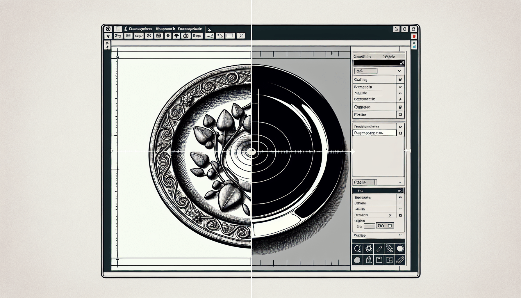
Once FreeCAD is open, you will need to import the image file that you want to use as a reference for creating the plate. In FreeCAD 0.21 and later versions, there is no longer a dedicated Image Workbench, so you will need to import the image using the Import function. To do this, go to the File menu, select Import, and choose the image file you want to import. Make sure the image file is in a format that is supported by FreeCAD, such as JPEG or PNG. Once you have selected the image file, click on the Open button to import it into your FreeCAD document.
Adjusting the image in FreeCAD
After importing the image into FreeCAD, you may need to make adjustments to the image to ensure it is aligned correctly and scaled properly. Double-click on the image in the tree view to bring up the image properties dialog. In this dialog, you can adjust various settings, such as the position, rotation, and scale of the image. For example, you can change the plane of the image, move it to the XY, XZ, or YZ plane, or rotate it to align it with the desired reference plane.
One of the most important adjustments you will need to make is to scale the image to match the actual size of the plate you want to create. To do this, click on the Calibrate button in the image properties dialog. Zoom in on a known dimension of the plate in the image and click on one corner of the dimension. Then, zoom out and click on the other corner of the dimension. In the calibration dialog, enter the actual size of the dimension and press Enter. The image will then be scaled accordingly, ensuring that the sketch you create based on this image will match the actual size of the plate.
Tracing the shape in a sketch
Creating a new sketch
Once you have adjusted the image in FreeCAD, you can proceed to create a new sketch based on the image. To create a new sketch, switch to the Part Design Workbench and create a new body if one does not already exist. In the new body, right-click and select “Create Sketch” from the context menu. This will open a new sketch editor where you can start tracing the outline of the plate.
Selecting the appropriate plane
When creating the new sketch, you will need to select the appropriate plane to sketch on. The plane you choose will depend on the orientation of the plate in the image and how you want to create the plate in FreeCAD. For example, if the plate is lying flat on a surface in the image, you may choose to sketch on the XY plane. If the plate is standing up vertically in the image, you may choose to sketch on the XZ or YZ plane. Selecting the correct plane is important to ensure that the sketch is aligned properly with the reference image.
Using the image as a reference
Once you have created the new sketch and selected the appropriate plane, you can start tracing the outline of the plate. Use the Line tool to draw straight lines and the Arc tool to draw curved lines. Take care to align the lines with the edges of the plate in the image as closely as possible. You can use the image as a reference to determine the position and shape of the lines in the sketch. Zoom in and out as needed to ensure accuracy in tracing the shape of the plate.
Tracing the outline of the plate
Continue tracing the outline of the plate by creating and connecting lines and arcs until you have completed the entire outline. Make sure to intersect the lines and arcs at the corners of the plate to create a closed shape. You can use the Trim Edge tool to remove any overlapping segments and ensure a clean and accurate outline. Pay attention to the details and dimensions of the plate in the image to ensure that the traced outline matches as closely as possible.
Find 3D Printing Accessories Here
Creating a body
Extruding the sketch to create a 3D body
Once you have traced the outline of the plate in the sketch, you can extrude the sketch to create a 3D body. Extruding the sketch will give thickness to the plate and turn it into a solid object that can be further processed in FreeCAD. To extrude the sketch, select the sketch in the tree view, right-click, and choose the “Pad” option from the context menu. In the Pad parameters dialog, specify the desired thickness for the plate and click OK. The sketch will be extruded into a 3D body with the specified thickness.
Adjusting the thickness of the plate
If the default thickness of the extruded plate does not match your requirements, you can adjust the thickness by modifying the pad parameters. To do this, select the 3D body in the tree view, right-click, and choose “Edit” from the context menu. In the Pad parameters dialog, change the thickness value to the desired value and click OK. The thickness of the plate will be updated accordingly, allowing you to create a plate with the desired dimensions.
Making paths in the Path/CAM Workbench
Switching to the Path Workbench
To proceed with the CNC machining process, you will need to switch to the Path Workbench in FreeCAD. The Path Workbench provides tools and functionality for creating toolpaths and generating G-code for CNC machines. To switch to the Path Workbench, go to the Workbench dropdown menu at the top of the FreeCAD window and select “Path” from the list of available workbenches.
Setting up the stock and outline of the plate
Once you are in the Path Workbench, you will need to set up the stock and outline of the plate. The stock represents the raw material from which the plate will be cut, and the outline represents the shape of the plate. To set up the stock, go to the Stock section in the Path Workbench and define the dimensions and position of the stock material. To set up the outline, go to the Job section in the Path Workbench and select the 3D body representing the plate as the outline.
Aligning the stock and outline properly
To ensure that the plate is cut accurately, it is important to align the stock and outline properly. This ensures that the CNC machine will cut the plate in the correct position and with the correct dimensions. Use the alignment tools in the Path Workbench to align the stock and outline as needed. This may involve moving, rotating, or scaling the stock or the outline to achieve the desired alignment.
Creating paths for milling
Once the stock and outline are aligned properly, you can proceed to create paths for milling the plate. Use the various path creation tools in the Path Workbench to create toolpaths that define how the CNC machine will cut the plate. These toolpaths may include roughing, finishing, and drilling operations, depending on the desired result. Take into consideration factors such as the cutting tool you will be using, the desired cutting depth, and the material properties of the plate when creating the toolpaths.
Setting up the path for milling on the CNC machine
Adjusting the z-axis position
Before you can mill the plate on the CNC machine, you will need to adjust the z-axis position to ensure that the cutting tool is at the correct height relative to the plate. This is important to ensure that the cutting tool does not cut too deep or too shallow into the material. Use the z-axis adjustment tools on your CNC machine to set the correct z-axis position based on the specifications provided by the tool manufacturer or the cutting parameters determined in the toolpath generation process.
Configuring the feed rate and spindle speed
In addition to adjusting the z-axis position, you will also need to configure the feed rate and spindle speed on the CNC machine. The feed rate determines how fast the cutting tool moves along the toolpaths, while the spindle speed determines how fast the tool rotates during cutting. These parameters are crucial for achieving the desired cutting results, such as smooth surfaces, accurate dimensions, and efficient material removal. Consult the user manual or documentation for your CNC machine to determine the appropriate feed rate and spindle speed settings for the material and cutting tool you are using.
Adding holes as holding points for cutting the plate
To ensure that the plate remains securely in place during the cutting process, it is common practice to add holes as holding points on the plate. These holes can be drilled into the plate prior to cutting, and screws or clamps can be inserted into the holes to secure the plate to the CNC machine bed or worktable. The size, number, and placement of these holding holes will depend on the size and shape of the plate, as well as the specific requirements of your CNC machine. Consult the CNC machine manual or documentation for guidance on the recommended hole sizes and placements.
Configuring the tool parameters
Before you can generate the G-code for the CNC machine, you will need to configure the tool parameters in the Path Workbench. This includes specifying the cutting tool you will be using, as well as its dimensions and cutting parameters. The cutting parameters may include values such as feed rate, spindle speed, cutting depth, clearance height, and tool compensation, among others. Consult the tool manufacturer’s specifications or cutting data sheet for the specific tool you are using to determine the appropriate values for these parameters.
Generating the G-code for the CNC machine
Once all the necessary parameters have been configured, you can generate the G-code for the CNC machine. G-code is a programming language that is used to control the movements and actions of CNC machines. In the Path Workbench, use the G-code generation tools to convert the toolpaths and tool parameters into G-code instructions that the CNC machine can understand. Once the G-code has been generated, save it as a separate file that can be loaded into the CNC machine for the milling process.
Creating separate operations for drilling holes and cutting
Creating the first operation for drilling holes
To create separate operations for drilling holes and cutting the plate, you will first need to create the operation for drilling the holes. In the Path Workbench, go to the Operations section and click on the “Add operation” button. Select the appropriate drilling operation from the list of available operations, such as “Drilling” or “Hole Drilling”. Configure the drilling parameters, such as the drill size, drill depth, hole spacing, and hole pattern. Ensure that the drilling operation is set up to drill the holding holes you added to the plate.
Configuring the drilling parameters
When configuring the drilling parameters for the drilling operation, consider factors such as the size and depth of the holes, the spacing between the holes, and the specific requirements of your CNC machine and cutting tools. Adjust the parameters as needed to ensure accurate and efficient drilling of the holding holes. For example, set the correct drill diameter to match the size of the screws or clamps you will be using for holding the plate.
Exporting the operation as a separate file
Once you have configured the drilling operation, you can export it as a separate file that can be loaded into the CNC machine. This allows you to perform the drilling process separately from the cutting process, if desired. In the Path Workbench, select the drilling operation in the tree view, right-click, and choose the “Export operation” option from the context menu. Save the operation as a separate file with a suitable name and file format, such as a G-code file. Make sure to note the location where the file is saved for easy access during the CNC machining process.
Creating the second operation for cutting
After creating the drilling operation, you can proceed to create the operation for cutting the plate. In the Path Workbench, click on the “Add operation” button again and select the appropriate cutting operation from the list. This may be an operation such as “Pocketing”, “Profile”, or “Contouring”. Configure the cutting parameters, such as the cutting tool, cutting depth, cutting strategy, and toolpath pattern. Ensure that the cutting operation is set up to cut the plate according to the desired dimensions and shape.
Configuring the cutting parameters
When configuring the cutting parameters for the cutting operation, take into consideration factors such as the type of cutting tool, the desired cutting depth, the material being cut, and the specific requirements of your CNC machine. Adjust the parameters as needed to achieve the desired cutting results, such as smooth surfaces, accurate dimensions, and efficient material removal. Consult the cutting tool manufacturer’s specifications or cutting data sheet for guidance on the recommended cutting parameters for your specific tool and material.
Exporting the operation as a separate file
Once you have configured the cutting operation, you can export it as a separate file that can be loaded into the CNC machine. This allows you to perform the cutting process separately from the drilling process, if desired. In the Path Workbench, select the cutting operation in the tree view, right-click, and choose the “Export operation” option from the context menu. Save the operation as a separate file with a suitable name and file format, such as a G-code file. Make sure to note the location where the file is saved for easy access during the CNC machining process.
Drilling holes and inserting screws
Loading the first file in the CNC machine
Once the drilling operation file has been exported, you can load it into the CNC machine for the drilling process. Use the software or control panel on the CNC machine to load the file. Follow the instructions provided by the CNC machine manufacturer to load the file correctly and set up the machine for the drilling operation. Ensure that the correct cutting tool is installed in the machine and that the plate is securely positioned on the machine bed or worktable.
Setting up the machine for drilling
Before starting the drilling process, make sure that the CNC machine is properly set up for drilling. This includes adjusting the z-axis position to match the starting position of the drilling operation, configuring the spindle speed and feed rate to match the drilling parameters, and ensuring that the holding holes in the plate are aligned with the drilling positions. Use the machine controls to make these adjustments according to the specifications provided by the drilling operation file and the CNC machine manufacturer.
Starting the drilling process
Once the machine is properly set up, you can start the drilling process. Initiate the drilling operation using the software or control panel on the CNC machine. The machine will begin drilling the holes as defined in the drilling operation file. Monitor the drilling process closely to ensure that the holes are being drilled to the correct depth and position. Make any necessary adjustments to the machine settings or plate position if deviations from the desired drilling results are observed.
Inserting screws in the drilled holes
After the drilling process is complete, you can insert screws or clamps into the drilled holes to secure the plate in its desired position. Carefully remove any excess debris or chips from the holes and align the screws or clamps with the holes. Use a suitable screwdriver or wrench to tighten the screws or clamps until the plate is securely held in place. Ensure that the screws or clamps are tightened evenly and do not damage the plate or interfere with the subsequent cutting process.
Cutting the plate on the CNC machine
Loading the second file in the CNC machine
With the plate securely held in place by the screws or clamps, you can proceed to load the second file into the CNC machine for the cutting process. Use the software or control panel on the CNC machine to load the file. Follow the instructions provided by the CNC machine manufacturer to load the file correctly and set up the machine for the cutting operation. Ensure that the correct cutting tool is installed in the machine and that the plate is still securely positioned on the machine bed or worktable.
Setting up the machine for cutting
Before starting the cutting process, make sure that the CNC machine is properly set up for cutting. This includes adjusting the z-axis position to match the starting position of the cutting operation, configuring the spindle speed and feed rate to match the cutting parameters, and ensuring that there is sufficient clearance for the cutting tool to move freely without hitting any obstacles. Use the machine controls to make these adjustments according to the specifications provided by the cutting operation file and the CNC machine manufacturer.
Starting the cutting process
Once the machine is properly set up, you can start the cutting process. Initiate the cutting operation using the software or control panel on the CNC machine. The machine will begin cutting the plate according to the toolpaths and cutting parameters defined in the cutting operation file. Monitor the cutting process closely to ensure that the plate is being cut to the correct dimensions and shape. Make any necessary adjustments to the machine settings or plate position if deviations from the desired cutting results are observed.
Completing the plate
Removing the screws
After the cutting process is complete, you can remove the screws or clamps from the plate. Carefully loosen and remove the screws or clamps using a suitable tool, such as a screwdriver or wrench. Take care not to damage the plate or any other components during the removal process. Set aside the screws or clamps for future use or disposal.
Comparing the new plate with the original
Once the screws or clamps have been removed, you can compare the new plate with the original plate or the desired specifications. Inspect the cut edges, surfaces, and dimensions of the new plate to ensure that they match the original plate or the intended design. Use measurement tools, such as calipers or rulers, to check the dimensions and tolerances of the new plate. Make any necessary adjustments or refinements to the new plate if deviations from the desired results are observed.
Concluding the overall accuracy of the process
After comparing the new plate with the original and evaluating its accuracy, you can conclude the overall accuracy of the process. Note any discrepancies or improvements that could be made to the process in the future. Consider factors such as the alignment of the stock and outline, the accuracy of the toolpaths, and the performance of the CNC machine. This evaluation will help you refine and improve the process for future projects.
Conclusion
Summary of the process
In this comprehensive article, we have explored the process of making a copy of a plate using an image and FreeCAD. We started by importing the image into FreeCAD and adjusting it to the correct size and orientation. Then, we traced the shape of the plate in a sketch using the image as a reference. Next, we created a 3D body by extruding the sketch and adjusted the thickness of the plate as needed. After that, we made paths in the Path/CAM Workbench to define the toolpaths for milling the plate on a CNC machine. We set up the path for milling, adjusted the z-axis position, configured the feed rate and spindle speed, and added holding holes for secure positioning. We created separate operations for drilling holes and cutting the plate, exported the operations as separate files, and performed the drilling process and cutting process on the CNC machine. Finally, we completed the plate by removing screws, comparing it to the original plate, and evaluating the overall accuracy of the process.
Final thoughts on using FreeCAD for CNC machining
Using FreeCAD for CNC machining offers numerous benefits and possibilities. FreeCAD is a powerful and versatile tool that allows you to import images, trace shapes, create 3D bodies, generate toolpaths, and export G-code for CNC machines. It provides a user-friendly interface and a wide range of tools and features that facilitate the CNC machining process. With FreeCAD, you can accurately replicate objects, customize designs, and achieve precise results. However, it is important to note that CNC machining requires proper knowledge and skills to ensure safe and efficient operation. Always follow the manufacturer’s instructions and guidelines when using a CNC machine and consult experts or professionals if needed.
Maintain Your 3D Printer with these Tools


