FLASHFORGE AD5M 3D Printer Fully Auto Calibration Print with 1-Click Max 600mm/s Speed, All-Metal CoreXY Structure Precise Printing, Easy-Maintenance Quick-Swap Nozzle, Print Size 220x220x220mm
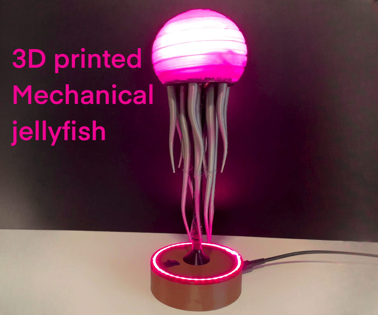
$259.00 (as of June 18, 2025 23:32 GMT +00:00 - More infoProduct prices and availability are accurate as of the date/time indicated and are subject to change. Any price and availability information displayed on [relevant Amazon Site(s), as applicable] at the time of purchase will apply to the purchase of this product.)Have you ever imagined art that moves, art that seems alive? Let’s journey together to discover how to craft a mesmerizing kinetic sculpture of interconnected gears and tentacles, a project blending creativity and engineering.
Mesmerizing Kinetic Sculpture of Interconnected Gears and Tentacles
This project isn’t just for hardcore engineers; it’s for anyone looking to blend art with engineering. This sculpture showcases the beauty of motion and the magic of mechanics.
Anycubic Coupon – $5 off $50+ sitewide with code DIY5OFF
Project Overview
This kinetic sculpture project merges art and mechanics into a captivating display. We’ll walk through the ins and outs of creating a kinetic sculpture with an interconnected gear system, perfect for enthusiasts and hobbyists.
- Dynamic Motion: The sculpture boasts a unique gearing system.
- Interactive Elements: Change colors and effects using an IR remote and LED strips.
- Quiet Operation: Enjoy the art without distracting noise.
- Easy Assembly: Follow clear instructions with 3D-printable files.
- Customizable Design: Add your personal touch to the project.
Key Features
The sculpture combines aesthetic appeal with technical functionality, ensuring the beauty of motion. Let’s examine the features that make this project unique.
- Dynamic motion with a unique gearing system
- Interactive elements with IR remote control to change colors and effects on LED strips
- Minimal noise for quiet operation
- Easy assembly with clear instructions and 3D-printable files
- Customizable design for personal touch

Anycubic Coupon – $5 off $50+ sitewide with code DIY5OFF
Design Requirements
Effective design blends complexity and minimalism, as we’ll discover. The sculpture needed to be visually appealing, easy to construct, and mechanically sound; let’s examine these requirements.
- Aesthetic Appeal: A balance of complexity and minimalism.
- 3D Printing: Easy to print on a standard 220mm bed.
- Easy Construction: Minimal complex joints and assembly steps.
- Satisfying Motion: A perfect 1:1 gear ratio.
- Minimal Noise: Reduced friction and vibration.
- Customizable: Interchangeable components.
CAD Design Process
The CAD (Computer-Aided Design) design phase is where we bring our ideas to life on the computer, testing functionality along the way. Using Fusion 360, we focused on creating a design that was functional, quiet, and easy to assemble.
- Fusion 360: The software used for design, focusing on functional gears and easy assembly.
- Gear Types: Incorporated spur, helical, bevel, and worm gears.
- Gear Parameters: Considered parameters like pressure angle, module, number of teeth, and backlash.
Modeling
Creating the 3D models of the sculpture’s components involves digital artistry and precision, so let’s investigate the modeling process. The sculpture comprises three main parts: gears, tentacles, and the head—each designed with specific constraints in mind.
- Three Main Parts: Gears, tentacles, and head.
- Constraints: Used constraints in Fusion 360 to control shape and size.
- Gearbox: Created a gearbox inside the head, with a maximum size of 65mm to house the gears.
Step-by-Step Instructions
Ready to build your mesmerizing kinetic sculpture? Let’s get started with straightforward instructions to ensure your project is successful.
Gathering Your Materials and Tools
Before you start, you’ve got to get your hands on the right tools. Here’s a list to ensure you’re well-prepared.
| Material/Tool | Use |
|---|---|
| 3D printer | To print the components of the sculpture. |
| Soldering kit | To connect electronic components. |
| Hot glue | To secure parts together. |
| Filament | The material used for 3D printing (PLA, ABS, etc.). |
| Wire | To connect electronic components. |
| Motor | To power the kinetic motion of the sculpture. |
| USB-C power supply | To provide power to the motor and electronics. |
| Switch | To turn the sculpture on and off. |
| Capacitor | To stabilize the power supply for the motor. |
| Ws2812b LED strip | To add customizable lighting effects. |
| IR receiver | To receive signals from the IR remote control. |
| Microcontroller | To control the LED strip and IR receiver. |
| Allen Wrenches | To secure the bolts that are holding the gear together. |
| Sandpaper | To fix imperfections on the 3D-printed parts |
| WD-40 | Use this to oil the gears and reduce noise. |
Printing the Components
With your materials ready, start by printing all the 3D models with your 3D printer. Ensure that each part is correctly oriented on the print bed to maximize quality and minimize support material.
- Download 3D Models: Obtain the .STL files for the gears, tentacles, and head from the project’s repository.
- Print Settings: Use a standard nozzle size (0.4mm) with a layer height of 0.2mm for a good balance of speed and detail.
- Material: PLA is a good choice for its ease of use and dimensional stability.
- Support Structures: Add supports where necessary, especially for overhanging parts of the tentacles and internal structures of the head.
- Infill: Use a 20% infill for most parts, but increase to 50% for gears that bear more load.
- Post-Processing: Remove any support material carefully and clean up the printed parts.
Assembling the Gearbox
The gearbox is the heart of your kinetic sculpture—where gears meet and motion begins. Build the gearbox inside the head by following these steps:
- Gear Placement: Place the gears inside the head, ensuring they mesh correctly. Start with the motor gear, then add intermediate gears, and finally, the main gear connected to the tentacles.
- Securing Gears: Use hot glue to fix each gear to the gearbox housing. Ensure that the gears are aligned so they rotate smoothly without obstructions.
- Wiring the Motor: Solder wires to the motor terminals and connect them to the switch. Then, connect the USB-C power supply to the switch, adding a capacitor in parallel to stabilize the power.
- Testing Rotation: Power the motor briefly to check that all gears rotate smoothly. Adjust their positions if necessary to reduce friction and noise.
Implementing the Tentacles
The tentacles, with their flowing motion, bring the sculpture to life—giving it character and charm. Now, let’s connect them, one by one.
- Attaching Tentacles: Connect the tentacles to the main gear using small screws or glue. Ensure they are evenly spaced around the gear for balanced motion.
- Testing Movement: Rotate the main gear manually to check that the tentacles move freely without any tangling or obstruction. Make adjustments as needed.
Setting Up the Electronics
Now, we turn to the electronic nervous system of your sculpture, where lights dance at your command. Configuring the electronics is where you infuse color and control into your kinetic creation.
-
LED Strip Installation: Attach the Ws2812b LED strip inside the head, around the base of the tentacles. Make sure the strip is securely fastened and the LEDs are facing outwards.
-
Wiring:
- Connect the LED strip to the microcontroller.
- Connect the IR receiver to the microcontroller.
- Ensure all connections are soldered securely.
-
Microcontroller Programming:
- Upload the provided code to the microcontroller.
- This code will control the LED colors and respond to IR remote commands.
-
Testing: Use the IR remote to change the LED colors and effects. Ensure the IR receiver is correctly oriented to pick up signals from the remote.
Here is a table of how the LED will operate!
| LED Colors | IR Remote |
|---|---|
| Red | Button A |
| Green | Button B |
| Blue | Button C |
Final Adjustments and Troubleshooting
At this stage, you’re about to breathe life into your sculpture. Now, let’s make any necessary tweaks.
-
Balance: Ensure the sculpture is balanced and stands firmly. Use a stable base to prevent it from tipping over during operation.
-
Noise Reduction:
- Apply lubricant (e.g., WD-40) to the gears to reduce friction and noise.
- Check for any parts rubbing against each other and adjust their positions.
-
Wiring Checks: Double-check all wire connections to ensure they are secure. Use a multimeter to verify continuity and voltage levels.
-
Final Test: Run the sculpture for an extended period to identify any issues. Monitor the motor temperature and adjust the load if it overheats.
Customization Ideas
Customization can make your kinetic sculpture truly one-of-a-kind. Here are some ideas to get you started:
- Replace Tentacles:
- Design and Print New Tentacles: Create tentacles with different shapes, lengths, or textures.
- Materials: Experiment with flexible filaments like TPU for added flexibility.
- Custom Gear Ratios:
- Adjust Gear Sizes: Change the sizes of the gears to alter the speed and torque of the tentacles.
- Impact: Smaller gears increase speed, while larger gears increase torque.
- Aesthetic Enhancements:
- Paint or Dye: Paint the 3D-printed parts in various colors to match your decor.
- Metallic Finishes: Use metallic paints or coatings to give the sculpture a premium look.
- Interactive Features:
- Sensors: Add sensors (e.g., light, sound, motion) to trigger different LED effects or movements.
- Remote Control: Enhance the IR remote functions with more complex commands.
- Base Design:
- Custom Base: Design a custom base with additional features like a built-in display, speakers, or wireless charging.
- Materials: Use wood, metal, or clear acrylic for a unique look.
Gear Parameters Explained
Understanding gear parameters is crucial for achieving smooth and efficient motion in your kinetic sculpture. Here’s a breakdown of key terms:
- Standard: The gear industry has set standards, such as those from AGMA and ISO, to ensure gears manufactured by different companies can work together.
- Pressure Angle: The angle between the line of force and the common tangent to the pitch circles. Common angles are 20° and 14.5°. A higher pressure angle results in stronger gears but can increase noise.
- Module: A unit of size that indicates the size of the gear teeth. It is the ratio of the pitch diameter to the number of teeth. The module affects the gear’s strength and size.
- Number of Teeth: The number of teeth on the gear. This number, along with the module, determines the gear’s pitch diameter and ratio.
- Backlash: The play or clearance between meshing gear teeth. Backlash is necessary to prevent the gears from binding due to thermal expansion and manufacturing inaccuracies.
- Root Fillet Radius: The radius of the curve at the base of the gear tooth. A larger fillet radius reduces stress concentrations and increases the tooth strength.
- Gear Thickness: The width of the gear along its axis. Thicker gears are generally stronger but may add weight and require more material.
- Hole Diameter: The diameter of the hole in the center of the gear, used for mounting the gear on a shaft. The hole diameter should match the shaft size.
| Parameter | Explanation |
|---|---|
| Standard | Gear follows standards sets by industry. |
| Pressure Angle | The angle between the line of force and the common tangent to the pitch circles. |
| Module | A unit of size that indicates the size of the gear teeth. |
| Number of Teeth | The number of teeth on the gear. |
| Backlash | The play or clearance between meshing gear teeth. |
| Root Fillet Radius | The radius of the curve at the base of the gear tooth. |
| Gear Thickness | The width of the gear along its axis. |
| Hole Diameter | The diameter of the hole in the center of the gear, used for mounting the gear on a shaft. |

Gear Types Explained
The sculpture uses a variety of gears, each serving a unique purpose in transferring motion, so let’s examine the different types of gears used:
- Spur Gears: These are the simplest type of gear, with straight teeth parallel to the axis of rotation. Spur gears are efficient for transmitting power between parallel shafts but can be noisy at high speeds.
- Helical Gears: These gears have teeth that are angled to the axis of rotation, allowing for smoother and quieter operation compared to spur gears. They can transmit power between parallel or non-parallel shafts.
- Bevel Gears: These gears have teeth that are angled to the axis of rotation and are used to transmit power between intersecting shafts, typically at a 90-degree angle.
- Worm Gears: These gears consist of a worm (a screw-like gear) that meshes with a worm wheel (a gear with teeth cut at an angle). Worm gears are used to transmit power between non-intersecting shafts and provide high gear ratios and torques.
| Gear Type | Purpose |
|---|---|
| Spur Gear | Power from parallel shafts |
| Helical Gear | Smoother and quieter operation compared to spur gears |
| Bevel Gears | A 90-degree angle power distribution |
| Worm Gears | Transmit power between non-intersecting shafts |
Anycubic Coupon – $5 off $50+ sitewide with code DIY5OFF
