ANYCUBIC Photon Mono 4, Resin 3D Printer with 7'' 10K Mono LCD Screen, Stable LighTurbo Light Source and 70mm/h Fast Printing, Print Volume 6.04'' x 3.42'' x 6.49''
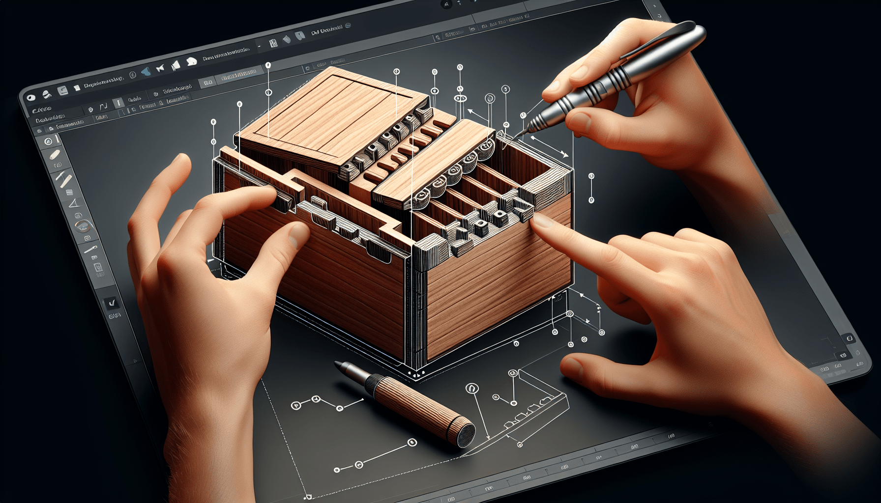
$159.99 (as of June 19, 2025 23:45 GMT +00:00 - More infoProduct prices and availability are accurate as of the date/time indicated and are subject to change. Any price and availability information displayed on [relevant Amazon Site(s), as applicable] at the time of purchase will apply to the purchase of this product.)In this captivating tutorial, you will learn how to create a sliding dovetail lid for a 3D printed box using Fusion 360. The tutorial covers a step-by-step process of creating the box, making it hollow, projecting the edges, cutting out the dovetail shape, creating the lid with clearance, and adding a sliding joint. User parameters are utilized to make the dimensions of the box adaptable, allowing you to customize it for different objects. The tutorial also emphasizes the importance of support material for the print and invites viewers to contribute ideas for preventing the lid from sliding completely out of the box. Overall, this tutorial provides a comprehensive guide to designing and printing a functional and versatile box with a sliding dovetail lid using Fusion 360.
In this creative Fusion 360 tutorial, Kevin Kennedy demonstrates how to create a 3D printable box with a sliding dovetail lid. Throughout the tutorial, he shares valuable tips and techniques, such as using user parameters to make the dimensions adaptable and organizing the design using components. Kevin also discusses the importance of support material for the print and invites viewers to contribute ideas for solving the issue of the lid sliding completely out of the box. With clear demonstrations and explanations, this tutorial is perfect for anyone interested in creating a customizable and practical storage solution using Fusion 360.
Creating the box
To create the sliding dovetail lid for the 3D printed box using Fusion 360, we need to start by designing the basic shape of the box. This can be done by using the primitive box shape in the solid modeling tab. We will set the dimensions of the box to our desired measurements, such as 50mm for width, 80mm for length, and 40mm for height. Once the dimensions are set, we can proceed to make the box hollow.
Making the box hollow
To make the box hollow, we will use the Shell command in Fusion 360. This command allows us to remove the inner material of the box, leaving only the walls with a specified thickness. In this case, we can set the thickness to 4mm using the Shell command. This will create walls around the box, making it hollow on the inside.
Adding user parameters for dimensions
To make the dimensions of the box adaptable, we can add user parameters in Fusion 360. User parameters are customizable variables that allow us to change the dimensions of the box easily. By creating new user parameter names, we can replace the fixed dimension values with the parameters. For example, we can create a user parameter named “Length” and set it to 80mm. Then, we can replace the dimension values of the box with the “Length” parameter. This way, if we need to change the length of the box, we can simply adjust the value of the “Length” parameter, and the dimensions of the box will update accordingly.
Creating the dovetail shape
The dovetail shape is a key component of the sliding dovetail lid. To create this shape, we will start by projecting the edges of the box onto a sketch. This will help us accurately define the angles and dimensions of the dovetail shape. We can use the project command in Fusion 360 to project the outer and inner edge lines onto our sketch.
Once the edges are projected, we can use the line command to sketch the dovetail shape. By drawing lines at specific angles and lengths, we can create a half of the dovetail shape. To complete the other half, we can use the mirror command to mirror the lines we created. This will give us a symmetrical dovetail shape.
Cutting out the dovetail shape
After creating the dovetail shape, we need to cut it out from the box to create the slot for the lid to slide into. To do this, we can use the Extrude command in Fusion 360. We will select the trapezoid shape created by the dovetail sketch as the profile and choose the back inside face of the box as the extent object. This will ensure that the cutout runs the entire length of the box.
Creating the lid
To create the lid, we need to design a component that will fit into the slot created by the dovetail shape. We will create a new component in Fusion 360 called “Lid” and ensure that it is on the same level as the box component. By projecting the current cutout shape onto a sketch on the front plane, we can offset the projection to factor in the clearance between the box and the lid. This clearance will allow the lid to slide in the actual 3D print.

Adding clearance to the lid
To add clearance to the lid and ensure a smooth sliding motion, we can offset the projected lines of the cutout shape by a specified distance. This distance will depend on the capabilities and calibration of your 3D printer. For reference, a clearance of 0.25mm has been successful in test prints. However, it is important to test and adjust the clearance based on your own printer’s nozzle size and calibration. Offset sketch lines can be edited at any time by double-clicking on the offset icon or using the “Edit Offset” option.
Designing the lid component
Once the clearance has been added to the lid, we can design the lid component itself. This can be done by sketching on the front plane of the lid component and creating a profile that matches the offset projection from the box. The lid profile should fit snugly into the slot created by the dovetail shape, allowing for easy sliding.
Organizing the design with components
To organize the design and keep track of the different parts, we can use components in Fusion 360. Components allow us to group relevant sketches and bodies together, making it easier to edit and modify the design. By creating separate components for the box and lid, we can keep them organized and apply specific features to each component. This will make it easier to manage and modify the design as needed.
Creating components
To create a component in Fusion 360, we can start by selecting the desired component level and choosing “New Component” from the right-click menu. This will create a new component that can be named accordingly. By setting the active component to the desired component, we can ensure that any new features or sketches will be applied to that component.
Managing components in the design
Once components have been created, we can manage them in the design by selecting and activating them as required. By selecting the desired component in the Browser, we can ensure that any changes or modifications will be applied to that specific component. This helps in keeping the design organized and allows for easier editing and modification of individual components.
Importance of support material for 3D printing
When 3D printing complex designs like the sliding dovetail lid, it is important to consider the use of support material. Support material helps in ensuring the printing process is successful and that the desired shape and features are achieved. It helps to support overhangs and bridges during the printing process, preventing them from collapsing or deforming. In Fusion 360, we can add support material to our design to ensure successful 3D printing.

Understanding the need for support
Due to the nature of the sliding dovetail lid design, there may be areas of overhang or unsupported regions during the printing process. This can result in unsuccessful prints or poor quality prints. By understanding the need for support material, we can take precautions and add it to the design where necessary. This will help to ensure the successful printing of the sliding dovetail lid.
Adding support material in Fusion 360
To add support material in Fusion 360, we can use the Generate Support command. This command analyzes the design and automatically generates support material in areas that require it. By using this feature, we can ensure that the sliding dovetail lid will be printed with the necessary support, resulting in a successful final product.
Limitations of the sliding dovetail lid design
While the sliding dovetail lid design is a great solution for creating a 3D printed box, it does have some limitations. One of the main limitations is the lack of a mechanism to prevent the lid from sliding completely out of the box. This can be problematic in certain situations where the lid needs to stay attached to the box. However, this limitation can be addressed through viewer input and suggestions for possible solutions.
Issue of the lid sliding completely out of the box
The design of the sliding dovetail lid allows for easy sliding in and out of the box. However, this means that the lid can slide completely out of the box, which can be undesirable in some cases. If the lid needs to stay attached to the box, the current design may not be suitable. This limitation can be addressed by finding a solution to prevent the lid from sliding out completely.
Inviting viewer input for possible solutions
To overcome the limitation of the sliding dovetail lid design, we can invite viewers to contribute their ideas and suggestions. By opening up the discussion and incorporating different perspectives, we can find innovative solutions to the problem of the lid sliding out completely. This collaborative approach will help in refining the design and creating a better final product.
Setting up user parameters
To make the dimensions of the box adaptable and customizable, we can set up user parameters in Fusion 360. User parameters allow us to easily change the dimensions of the box without having to modify individual sketch dimensions. By using the Parameters Dialog in Fusion 360, we can create new user parameter names and replace dimension values with parameters.

Using the Parameters Dialog in Fusion 360
The Parameters Dialog in Fusion 360 allows us to create, edit, and manage user parameters. It provides a user-friendly interface where we can view and modify existing parameters, as well as create new ones. By using this dialog, we can easily set up and adjust user parameters to make our design more adaptable.
Creating new user parameter names
To create new user parameter names in Fusion 360, we can navigate to the Parameters Dialog and click on the “New Parameter” button. This will open a window where we can provide a name for the parameter and set its initial value. By giving the parameter a descriptive name, we can easily identify its purpose and function in our design.
Replacing dimension values with parameters
Once we have created the necessary user parameters, we can replace the fixed dimension values in our design with these parameters. This can be done by double-clicking on a dimension and typing in the name of the parameter instead of a specific value. By doing this, the dimension will be linked to the parameter, allowing us to easily modify it in the Parameters Dialog.
Adjusting parameters and dimensions
To adjust the dimensions of the box using the user parameters, we can simply modify the values of the parameters in the Parameters Dialog. This will automatically update the dimensions of the box in the design. By changing the parameter values, we can easily adapt the dimensions of the box to fit our specific needs and requirements.
Changing box dimensions
To change the dimensions of the box, we can modify the values of the user parameters that are linked to the corresponding dimensions. By adjusting the parameter values, the dimensions of the box will automatically update to reflect the changes. This allows us to easily customize the size and shape of the box without having to manually edit individual dimensions.
Setting the thickness parameter
The thickness of the box can be set using a user parameter. By creating a user parameter named “Thickness” and linking it to the thickness dimension of the box, we can easily adjust the thickness of the box. This parameter can be modified in the Parameters Dialog, allowing us to adapt the thickness of the box to our specific requirements.
Adjusting clearance parameter
The clearance between the box and the lid can be set using a user parameter. By creating a user parameter named “Clearance” and linking it to the offset value of the lid projection, we can easily modify the clearance. This parameter can be adjusted in the Parameters Dialog, allowing us to fine-tune the clearance to ensure smooth sliding of the lid.
Adding additional features
In addition to the basic sliding dovetail lid design, we can add additional features to enhance the functionality and aesthetics of the box. One such feature is adding a divot to the lid. This can be done by creating a new sketch on the lid component and using the Extrude command to cut out a divot shape. Another feature that can be added is a sliding joint to animate the lid. This can be achieved using the As-Built Joint feature in Fusion 360.
Adding divot to the lid
To add a divot to the lid, we can create a new sketch on the lid component and use the Extrude command to cut out the divot shape. By sketching the desired shape and using the “Cut” option in the Extrude command, we can create a recessed area on the lid. This divot can serve as a thumb hold, making it easier to slide the lid open and closed.
Creating a sliding joint
To animate the lid and create a sliding motion, we can add a sliding joint to the lid component. This can be achieved using the As-Built Joint feature in Fusion 360. By hiding the lid component and setting the joint to slide on the Y-axis, we can create an animation that simulates the sliding motion of the lid. The joint limits can be adjusted to control the movement of the lid and fine-tune the animation.
Conclusion
In conclusion, creating a sliding dovetail lid for a 3D printed box using Fusion 360 is a rewarding and creative project. By following the steps outlined in this tutorial, you can design a customizable box with a functional and stylish sliding lid. The use of user parameters allows for easy modification of the box dimensions, while the addition of support material ensures successful 3D printing. Although the design has some limitations, viewer input and collaboration can lead to innovative solutions. With the final touches of parameter adjustments and additional features such as a divot and sliding joint, you can create a unique and practical sliding dovetail lid for your 3D printed box. This tutorial is available to Patreon supporters, who can further explore the design process and gain access to additional resources. So, get creative and start designing your own sliding dovetail lid today!


