
Creality K1 Max 3D Printer Smart AI Monitoring 600mm/s High-Speed Printing XY Design Auto Leveling Large Build Volume 11.81x11.81x11.81in Dual-Gear Extruder for Precise and Efficient Printing
$899.00 (as of June 18, 2025 23:32 GMT +00:00 - More infoProduct prices and availability are accurate as of the date/time indicated and are subject to change. Any price and availability information displayed on [relevant Amazon Site(s), as applicable] at the time of purchase will apply to the purchase of this product.)Are you ready to unlock the secrets of gear creation in Fusion 360?

Anycubic Coupon – $5 off $50+ sitewide with code DIY5OFF
What is Fusion 360?
Fusion 360 is a powerful CAD design software that allows you to create complex designs and models with ease. It’s a popular tool among designers, engineers, and makers, and is widely used in various industries, from aerospace to automotive.
Why Create a Gear in Fusion 360?
Creating a gear in Fusion 360 can be a fun and rewarding project, and is a great way to learn the basics of CAD design. Gears are an essential component in many mechanical systems, and understanding how to create them can open up a world of possibilities for your designs.

Anycubic Coupon – $5 off $50+ sitewide with code DIY5OFF
Supplies Needed
To get started, you’ll need Fusion 360 software, which can be downloaded from the Autodesk website. You can also use a pre-made gear design as a reference, which can be downloaded from the internet or created by yourself.
Step 1: Creating the Base Circle
To start creating your gear, open Fusion 360 and click on the “Create Sketch” button. Choose the “Center Diameter Circle” tool and draw a circle in the middle of the screen. Make sure the circle is centered and adjust the diameter to your desired size.
| Tool | Function |
|---|---|
| Create Sketch | Start a new sketch |
| Center Diameter Circle | Draw a circle with a central diameter |
Understanding the Center Diameter Circle Tool
The Center Diameter Circle tool is used to draw a circle with a central diameter. This tool is useful for creating circles with a specific diameter, and is often used in gear design.

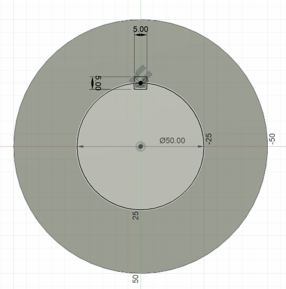
Step 2: Adding the Inner Circle and Keyway
Once you’ve created the base circle, you’ll need to add an inner circle and a keyway. Click on the “Create Sketch” button again and choose the “Center Diameter Circle” tool. Draw a second circle inside the first one, making sure it’s smaller in diameter. Then, click on the “Create” button and choose the “Center Diameter Rectangle” tool. Draw a rectangle on the outer line of the inner circle, making sure it’s centered.
| Tool | Function |
|---|---|
| Create Sketch | Start a new sketch |
| Center Diameter Circle | Draw a circle with a central diameter |
| Center Diameter Rectangle | Draw a rectangle with a central diameter |
Understanding the Keyway
A keyway is a narrow slot or channel cut into a gear or shaft, used to prevent the gear from rotating independently. Keyways are an essential component in many mechanical systems, and are often used in gear design.
Step 3: Hollowing the Gear
To hollow out the gear, click on the “Extrude” button and select the inner circle and rectangle. Then, push the extrusion through the gear to create a hollow center.
| Tool | Function |
|---|---|
| Extrude | Create a 3D shape from a 2D sketch |
Understanding the Extrude Tool
The Extrude tool is used to create a 3D shape from a 2D sketch. This tool is useful for creating complex shapes and designs, and is often used in gear design.

Step 4: Creating Additional Circles
To add additional circles to your gear, click on the “Create Sketch” button and choose the “Center Diameter Circle” tool. Draw two more circles around the inner circle, making sure they’re smaller in diameter. Then, click on the “Extrude” button and push the extrusion inside the gear.
| Tool | Function |
|---|---|
| Create Sketch | Start a new sketch |
| Center Diameter Circle | Draw a circle with a central diameter |
| Extrude | Create a 3D shape from a 2D sketch |
Understanding the Role of Additional Circles
Additional circles are used to add texture and detail to your gear. They can also be used to create a specific design or pattern.
Step 5: Mirroring the Feature
To mirror the feature, click on the “Create” button and choose the “Mirror” tool. Select the last circle you drew and click on the “Mirror Plane” button. Then, choose the yellow side inside the gear.
| Tool | Function |
|---|---|
| Create | Start a new feature |
| Mirror | Mirror a feature or body |
Understanding the Mirror Tool
The Mirror tool is used to create a mirrored copy of a feature or body. This tool is useful for creating symmetrical designs and is often used in gear design.

Step 6: Designing the Gear Teeth
To design the gear teeth, click on the “Create Sketch” button and choose the “Line” or “Conic Curve” tool. Draw a line or curve on the outer circle, making sure it’s connected to the other lines or curves.
| Tool | Function |
|---|---|
| Create Sketch | Start a new sketch |
| Line | Draw a line |
| Conic Curve | Draw a conic curve |
Understanding the Role of Gear Teeth
Gear teeth are used to transmit power and motion between gears. They’re an essential component in many mechanical systems, and are often used in gear design.
Step 7: Finishing Up
To finish your gear design, click on the “Extrude” button and pull the extrusion back to create a hollow center. Then, click on the “Create” button and choose the “Pattern” tool. Select the “Circular Pattern” option and choose the object type as “Features”. Click on the part you just emptied out and choose the lateral side of the gear. Finally, add as many teeth as you want.
| Tool | Function |
|---|---|
| Extrude | Create a 3D shape from a 2D sketch |
| Create | Start a new feature |
| Pattern | Create a pattern of features or bodies |
Congratulations! You’ve just created a gear in Fusion 360.
Anycubic Coupon – $5 off $50+ sitewide with code DIY5OFF
ELEGOO PLA Filament 1.75mm Black 1KG, 3D Printer Filament Dimensional Accuracy +/- 0.02mm, 1kg Spool(2.2lbs) Fit Most FDM 3D Printers
$13.99 (as of June 18, 2025 23:32 GMT +00:00 - More infoProduct prices and availability are accurate as of the date/time indicated and are subject to change. Any price and availability information displayed on [relevant Amazon Site(s), as applicable] at the time of purchase will apply to the purchase of this product.)
SUNLU PLA Plus Filament 1.75mm Black 1KG, Neatly Wound 3D Printer Filament 1.75mm, PLA+ 1000g, Dimensional Accuracy +/- 0.02 mm, Fit Most FDM 3D Printers, 1kg Spool (2.2lbs), Black
$14.99 (as of June 18, 2025 23:32 GMT +00:00 - More infoProduct prices and availability are accurate as of the date/time indicated and are subject to change. Any price and availability information displayed on [relevant Amazon Site(s), as applicable] at the time of purchase will apply to the purchase of this product.)
Creality K2 Plus Combo 3D Printer, Multi Color Printing with New CFS, Max 600mm/s Printing Speed, Full-auto Leveling, Next-Gen Direct Drive Extruder, Dual Al Camera, Build Volume 350 * 350 * 350mm
$1,349.00 (as of June 18, 2025 23:32 GMT +00:00 - More infoProduct prices and availability are accurate as of the date/time indicated and are subject to change. Any price and availability information displayed on [relevant Amazon Site(s), as applicable] at the time of purchase will apply to the purchase of this product.)
3D Scanning Tracking Markers Dots,6mm Diffuse Reflection 3D PositioningTarget Stickers,HogarDeco Reference Point Markers for Industrial and Interest Optical 3D Scanner (300pcs, Inner 6mm Outer 10mm
$9.99 (as of June 18, 2025 23:32 GMT +00:00 - More infoProduct prices and availability are accurate as of the date/time indicated and are subject to change. Any price and availability information displayed on [relevant Amazon Site(s), as applicable] at the time of purchase will apply to the purchase of this product.)